Nissan Versa Note. Manual - part 272
EC-70
< ECU DIAGNOSIS INFORMATION >
[HR16DE]
ECM
ECU DIAGNOSIS INFORMATION
ECM
Reference Value
INFOID:0000000009020642
VALUES ON THE DIAGNOSIS TOOL
NOTE:
• The following table includes information (items) inapplicable to this vehicle. For information (items) applica-
ble to this vehicle, refer to CONSULT display items.
• Numerical values in the following table are reference values.
• These values are input/output values that ECM receives/transmits and may differ from actual operations.
Example: The ignition timing shown by the timing light may differ from the ignition timing displayed on the
data monitor.
This occurs because the timing light shows a value calculated by ECM according to signals received from
the camshaft position sensor and other sensors related to ignition timing.
• For outlines of following items, refer to
.
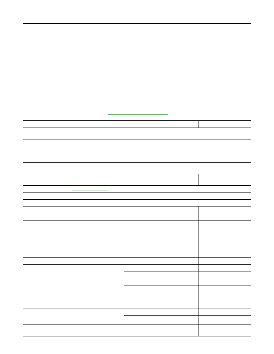
Monitor Item
Condition
Values/Status
IDLE REQUEST
NOTE:
The item is indicated, but not used.
MIL ON REQUEST
NOTE:
The item is indicated, but not used.
ENGINE NO-LOAD
NOTE:
The item is indicated, but not used.
READY STATE
NOTE:
The item is indicated, but not used.
ENG SPEED
• Run engine and compare CONSULT value with the tachometer indication.
Almost the same speed as
the tachometer indication.
MAS A/F SE-B1
See
.
B/FUEL SCHDL
See
.
A/F ALPHA-B1
See
.
COOLAN TEMP/S
• Engine: After warming up
More than 70
°C (158F)
A/F SEN1 (B1)
• Engine: After warming up
Maintaining engine speed at 2,000 rpm
Fluctuates around 2.2 V
HO2S2 (B1)
• Revving engine from idle up to 3,000 rpm quickly after the following conditions
are met.
- Engine: After warming up
- After keeping engine speed between 3,500 and 4,000 rpm for 1 minute and at
idle for 1 minute under no load
0 - 0.3 V
←→ Approx. 0.6 -
1.0 V
HO2S2 MNTR (B1)
LEAN
←→ RICH
VHCL SPEED SE
• Turn drive wheels and compare CONSULT value with the speedometer indi-
cation.
Almost the same speed as
speedometer indication
BATTERY VOLT
• Ignition switch: ON (Engine stopped)
11 - 14 V
ACCEL SEN 1
• Ignition switch: ON
(Engine stopped)
Accelerator pedal: Fully released
0.6 - 0.9 V
Accelerator pedal: Fully depressed
4.0 - 4.8 V
ACCEL SEN 2
• Ignition switch: ON
(Engine stopped)
Accelerator pedal: Fully released
0.6 - 0.9 V
Accelerator pedal: Fully depressed
3.9 - 4.8 V
TP SEN 1-B1
• Ignition switch: ON
(Engine stopped)
• Shift lever: 1st
Accelerator pedal: Fully released
More than 0.36 V
Accelerator pedal: Fully depressed
Less than 4.75 V
TP SEN 2-B1
• Ignition switch: ON
(Engine stopped)
• Shift lever:1st
Accelerator pedal: Fully released
More than 0.36 V
Accelerator pedal: Fully depressed
Less than 4.75 V
FUEL T/TMP SE
• Ignition switch: ON
Indicates fuel tank tempera-
ture