Nissan Versa Note. Manual - part 254


  Index      Nissan     Nissan Versa Note (2014 year) - Service and Repair Manual


Search            


Content   ..  252  253  254  255   ..


Nissan Versa Note. Manual - part 254


DOOR SWITCH

DLK-301

< REMOVAL AND INSTALLATION >

[WITHOUT INTELLIGENT KEY SYSTEM]

C

D

E

F

G

H

I

J

L

M

A

B

DLK

N

O

P

DOOR SWITCH

Removal and Installation

INFOID:0000000009645220
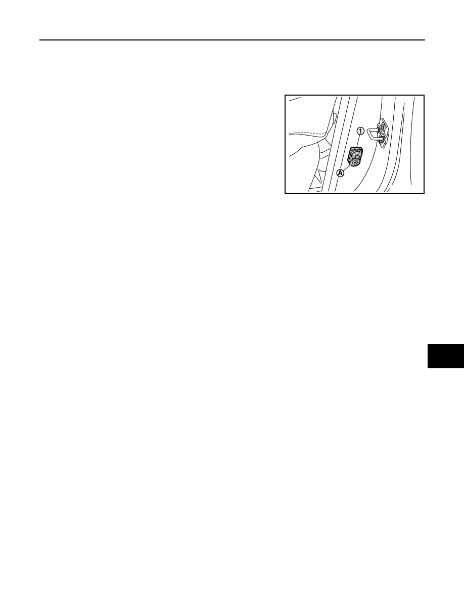
REMOVAL

1. Remove the door switch bolt (A).
2. Disconnect the harness connector and remove door switch (1).

INSTALLATION

Installation is in the reverse order of removal.

JMKIA2173ZZ

DLK-302

< REMOVAL AND INSTALLATION >

[WITHOUT INTELLIGENT KEY SYSTEM]

REMOTE KEYLESS ENTRY RECEIVER

REMOTE KEYLESS ENTRY RECEIVER

Removal and Installation

INFOID:0000000009645227

REMOVAL

1. Remove glove box assembly. Refer to 

IP-25, "Removal and Installation"

.

2. Remove remote keyless entry receiver bolt (A).
3. Disconnect the harness connector and remove remote keyless

entry receiver (1)

INSTALLATION

Installation is in the reverse order of removal.

JMKIA7947ZZ

KEYFOB BATTERY

DLK-303

< REMOVAL AND INSTALLATION >

[WITHOUT INTELLIGENT KEY SYSTEM]

C

D

E

F

G

H

I

J

L

M

A

B

DLK

N

O

P

KEYFOB BATTERY

Removal and Installation

INFOID:0000000009671243

REPLACEMENT

1. Remove screw from the rear of keyfob.

2. Place the key with the lower case facing up. Use a suitable tool wrapped with tape between upper case

and lower case and separate the lower case from the upper case.

CAUTION:

• Do not touch the circuit board or battery terminal. Doing so could cause the keyfob to malfunc-

tion

• The keyfob is water-resistant. However, if it does get wet, immediately wipe it dry. 

3. When replacing the circuit board assembly, remove circuit board assembly from the upper case.

[Circuit board assembly: Switch rubber + Board surface]

CAUTION:

Do not touch the printed circuits directly.

4. Remove the battery from the lower case and replace it.

CAUTION:

When replacing battery, keep dirt, grease, and other foreign materials off the electrode contact

area.

5. After replacement, fit the lower and upper cases together and tighten with the screw.

CAUTION:

After replacing the battery, Be sure to check that door locking operates normally using the keyfob.

Refer to 

DLK-240, "Component Function Check"

.

Battery replacement

: Coin-type lithium battery 
(CR1620)

EC-1

ENGINE

C

D

E

F

G

H

I

J

K

L

M

SECTION 

EC

A

EC

N

O

P

CONTENTS

ENGINE CONTROL SYSTEM

HR16DE

PRECAUTION ...............................................

8

PRECAUTIONS ...................................................

8

Precaution for Supplemental Restraint System 
(SRS) "AIR BAG" and "SEAT BELT PRE-TEN-
SIONER" .................................................................
..

8

Precaution for Procedure without Cowl Top Cover ......

8

On Board Diagnostic (OBD) System of Engine 
and CVT  ..................................................................
..

8

General Precautions  .................................................

9

PREPARATION ...........................................

12

PREPARATION ..................................................

12

Special Service Tools ..............................................

12

Commercial Service Tools  ......................................

12

SYSTEM DESCRIPTION  .............................

14

COMPONENT PARTS  .......................................

14

ENGINE CONTROL SYSTEM ...................................

14

ENGINE CONTROL SYSTEM : 
Component Parts Location ....................................

14

ENGINE CONTROL SYSTEM : Component De-
scription ...................................................................

17

Accelerator Pedal Position Sensor ..........................

18

Air Fuel Ratio Sensor 1  ...........................................

19

Air Fuel Ratio Sensor 1 Heater  ...............................

19

Camshaft Position Sensor .......................................

19

Clutch Pedal Position Switch  ..................................

20

Cooling Fan .............................................................

20

Crankshaft Position Sensor .....................................

20

ECM ........................................................................

20

Electric Throttle Control Actuator  ............................

21

Engine Coolant Temperature Sensor ......................

21

Engine Oil Pressure Sensor ....................................

21

Engine Oil Temperature Sensor ..............................

21

EVAP Canister Purge Volume Control Solenoid 
Valve .......................................................................

22

EVAP Canister Vent Control Valve ..........................

22

EVAP Control System Pressure Sensor ..................

22

Exhaust Valve Timing Control Solenoid Valve  ........

23

Fuel Injector .............................................................

23

Fuel Pump  ...............................................................

23

Heated Oxygen Sensor 2  ........................................

24

Heated Oxygen Sensor 2 Heater  ............................

24

Ignition Coil With Power Transistor  .........................

24

Intake Air Temperature Sensor  ...............................

24

Intake Valve Timing Control Solenoid Valve  ...........

25

Knock Sensor  ..........................................................

25

Battery Current Sensor (With Battery Tempera-
ture Sensor) .............................................................

25

Malfunction Indicator Lamp (MIL)  ............................

26

Mass Air Flow Sensor ..............................................

26

Oil Pressure Warning Lamp ....................................

26

Refrigerant Pressure Sensor  ...................................

27

Stop Lamp Switch & ASCD Brake Switch  ...............

27

Throttle Control Motor ..............................................

27

Throttle Control Motor Relay  ...................................

27

Throttle Position Sensor  ..........................................

27

ASCD Steering Switch .............................................

27

STRUCTURE AND OPERATION  .....................

28

Positive Crankcase Ventilation  ................................

28

On Board Refueling Vapor Recovery (ORVR)  ........

29

SYSTEM ............................................................

30

ENGINE CONTROL SYSTEM  ...................................

30

ENGINE CONTROL SYSTEM : System Diagram ....

30

ENGINE CONTROL SYSTEM : System Descrip-
tion ...........................................................................

31

MULTIPORT FUEL INJECTION SYSTEM  ................

31

MULTIPORT FUEL INJECTION SYSTEM : 
System Diagram .....................................................

32

MULTIPORT FUEL INJECTION SYSTEM : Sys-
tem Description ........................................................

32

ELECTRIC IGNITION SYSTEM .................................

35


Content   ..  252  253  254  255   ..