Nissan Versa Note. Manual - part 119


  Index      Nissan     Nissan Versa Note (2014 year) - Service and Repair Manual


Search            


Content   ..  117  118  119  120   ..


Nissan Versa Note. Manual - part 119


BRC-40

< ECU DIAGNOSIS INFORMATION >

[VDC/TCS/ABS]

ABS ACTUATOR AND ELECTRIC UNIT (CONTROL UNIT)

DTC Inspection Priority Chart

INFOID:0000000009364898

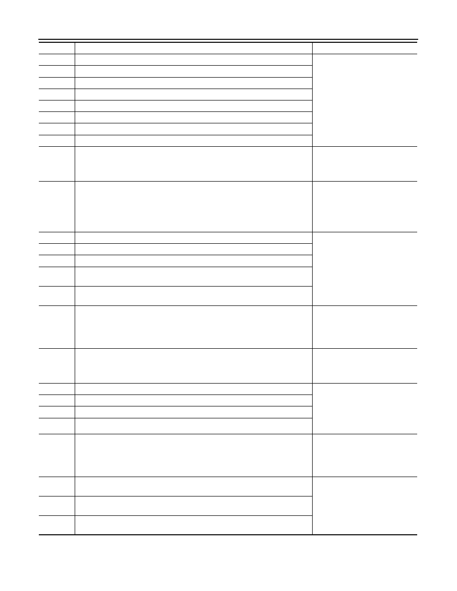
When multiple DTCs are displayed simultaneously, check each one using the following priority list.

C1120

When a malfunction is detected in front LH ABS IN valve.

The following functions are sus-
pended:
• VDC
• TCS
• ABS
• EBD

C1121

When a malfunction is detected in front LH ABS OUT valve.

C1122

When a malfunction is detected in front RH ABS IN valve.

C1123

When a malfunction is detected in front RH ABS OUT valve.

C1124

When a malfunction is detected in rear LH ABS IN valve.

C1125

When a malfunction is detected in rear LH ABS OUT valve.

C1126

When a malfunction is detected in rear RH ABS IN valve.

C1127

When a malfunction is detected in rear RH ABS OUT valve.

C1130

When a malfunction is detected in ECM system.

The following functions are sus-
pended:
• VDC
• TCS

C1140

When a malfunction is detected in actuator relay.

The following functions are sus-
pended:
• VDC
• TCS
• ABS
• EBD

C1142

When a malfunction is detected in VDC pressure sensor.

The following functions are sus-
pended:
• VDC
• TCS

C1143

When a malfunction is detected in steering angle sensor.

C1144

When neutral position adjustment of steering angle sensor is not complete.

C1145

When a malfunction is detected in yaw rate signal, or signal line of yaw rate/side/
decel G sensor is open or shorted.

C1146

When a malfunction is detected in side G signal, or signal line of yaw rate/side/decel 
G sensor is open or shorted.

C1153

When ABS actuator and electric unit (control unit) is malfunctioning. (Pressure in-
crease is too much or too little.)

The following functions are sus-
pended:
• VDC
• TCS
• ABS

C1155

When brake fluid level low signal is detected.

The following functions are sus-
pended:
• VDC
• TCS

C1164

When a malfunction is detected in cut valve 1.

The following functions are sus-
pended:
• VDC
• TCS
• ABS
• EBD

C1165

When a malfunction is detected in cut valve 2.

C1166

When a malfunction is detected in suction valve 1.

C1167

When a malfunction is detected in suction valve 2.

C1170

When the information in ABS actuator and electric unit (control unit) is not the same.

The following functions are sus-
pended:
• VDC
• TCS
• ABS

U1000

When CAN communication signal is not continuously transmitted or received for 2 
seconds or more.

The following functions are sus-
pended:
• VDC
• TCS

U1002

When ABS actuator and electric unit (control unit) is not transmitting or receiving 
CAN communication signal for 2 seconds or less.

U1010

When detectring error during the initial diagnosis of CAN controller of ABS actuator 
and electric unit (control unit)

DTC

Malfunction detected condition

Fail-safe condition

ABS ACTUATOR AND ELECTRIC UNIT (CONTROL UNIT)

BRC-41

< ECU DIAGNOSIS INFORMATION >

[VDC/TCS/ABS]

C

D

E

G

H

I

J

K

L

M

A

B

BRC

N

O

P

DTC Index

INFOID:0000000009364899

Priority

Detected item (DTC)

1

• U1000 CAN COMM CIRCUIT
• U1002 SYSTEM COMM(CAN)
• U1010 CAN CONTROLLER CIRCUIT

2

• C1110 CONTROLLER FAILURE
• C1153 EMERGENCY BRAKE
• C1170 VARIANT CORDING

3

• C1130 ENGINE SIGNAL 1
• C1144 ST ANG SEN SIGNAL

4

• C1109 BATTERY VOLTAGE [ABNORMAL]
• C1111 PUMP MOTOR
• C1140  ACTUATOR  RLY

5

• C1101 RR RH SENSOR-1
• C1102 RR LH SENSOR-1
• C1103 FR RH SENSOR-1
• C1104 FR LH SENSOR-1
• C1105 RR RH SENSOR-2
• C1106 RR LH SENSOR-2
• C1107 FR RH SENSOR-2
• C1108 FR LH SENSOR-2
• C1115 ABS SENSOR [ABNORMAL SIGNAL]
• C1116 STOP LAMP SW
• C1120 FR LH IN ABS SOL
• C1121 FR LH OUT ABS SOL
• C1122 FR RH IN ABS SOL
• C1123 FR RH OUT ABS SOL
• C1124 RR LH IN ABS SOL
• C1125 RR LH OUT ABS SOL
• C1126 RR RH IN ABS SOL
• C1127 RR RH OUT ABS SOL
• C1142 PRESS SEN CIRCUIT
• C1143 ST ANG SEN CIRCUIT
• C1145 YAW RATE SENSOR
• C1146 SIDE G-SEN CIRCUIT
• C1164  CV1
• C1165  CV2
• C1166 SV1
• C1167 SV2

6

• C1155 BR FLUID LEVEL LOW

DTC

Items (CONSULT screen terms)

Reference

C1101

RR RH SENSOR-1

BRC-55, "DTC Logic"

C1102

RR LH SENSOR-1

C1103

FR RH SENSOR-1

C1104

FR LH SENSOR-1

C1105

RR RH SENSOR-2

BRC-59, "DTC Logic"

C1106

RR LH SENSOR-2

C1107

FR RH SENSOR-2

C1108

FR LH SENSOR-2

C1109

BATTERY VOLTAGE [ABNORMAL]

BRC-61, "DTC Logic"

C1110

CONTROLLER FAILURE

BRC-63, "DTC Logic"

C1111

PUMP MOTOR

BRC-64, "DTC Logic"

C1115

ABS SENSOR [ABNORMAL SIGNAL]

BRC-66, "DTC Logic"

BRC-42

< ECU DIAGNOSIS INFORMATION >

[VDC/TCS/ABS]

ABS ACTUATOR AND ELECTRIC UNIT (CONTROL UNIT)

C1116

STOP LAMP SW

BRC-68, "DTC Logic"

C1120

FR LH IN ABS SOL

BRC-70, "DTC Logic"

C1121

FR LH OUT ABS SOL

BRC-72, "DTC Logic"

C1122

FR RH IN ABS SOL

BRC-70, "DTC Logic"

C1123

FR RH OUT ABS SOL

BRC-72, "DTC Logic"

C1124

RR LH IN ABS SOL

BRC-70, "DTC Logic"

C1125

RR LH OUT ABS SOL

BRC-72, "DTC Logic"

C1126

RR RH IN ABS SOL

BRC-70, "DTC Logic"

C1127

RR RH OUT ABS SOL

BRC-72, "DTC Logic"

C1130

ENGINE SIGNAL 1

BRC-74, "DTC Logic"

C1140

ACTUATOR RLY

BRC-75, "DTC Logic"

C1142

PRESS SEN CIRCUIT

BRC-77, "DTC Logic"

C1143

ST ANG SEN CIRCUIT

BRC-78, "DTC Logic"

C1144

ST ANG SEN SIGNAL

BRC-80, "DTC Logic"

C1145

YAW RATE SENSOR

BRC-81, "DTC Logic"

C1146

SIDE G-SEN CIRCUIT

C1155

BR FLUID LEVEL LOW

BRC-82, "DTC Logic"

C1164

CV 1

BRC-84, "DTC Logic"

C1165

CV 2

C1166

SV 1

C1167

SV 2

U1000

CAN COMM CIRCUIT

BRC-86, "DTC Logic"

U1002

SYSTEM COMM(CAN)

BRC-87, "DTC Logic"

U1010

CAN CONTROLLER CIRCUIT

BRC-88, "DTC Logic"

DTC

Items (CONSULT screen terms)

Reference

BRAKE CONTROL SYSTEM

BRC-43

< WIRING DIAGRAM >

[VDC/TCS/ABS]

C

D

E

G

H

I

J

K

L

M

A

B

BRC

N

O

P

WIRING DIAGRAM

BRAKE CONTROL SYSTEM

Wiring Diagram

INFOID:0000000009364900

AAFWA0113GB


Content   ..  117  118  119  120   ..