Nissan Versa Note. Manual - part 74
BCS
BCM
BCS-33
< ECU DIAGNOSIS INFORMATION >
[WITH INTELLIGENT KEY SYSTEM]
C
D
E
F
G
H
I
J
K
L
B
A
O
P
N
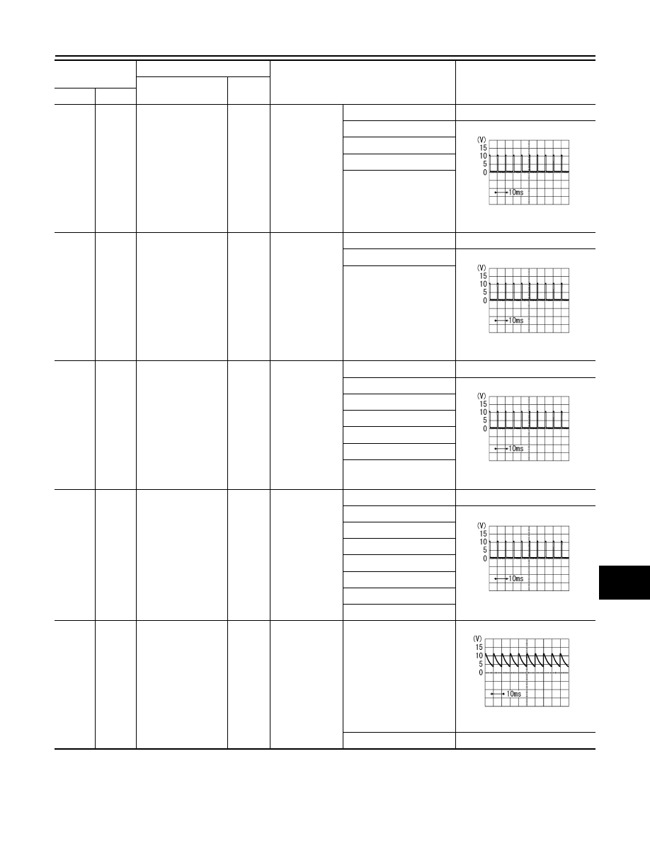
3
(Y)
Ground INPUT 4 signal
Input
Combination
switch
OFF
0 V
TURN LH
1.0 V
PASSING
HEADLAMP 2
FR FOG
4
(L)
Ground INPUT 3 signal
Input
Combination
switch
OFF
0 V
FR WIPER LO
1.0 V
FR WIPER INT
(any intermittent position)
5
(G)
Ground INPUT 2 signal
Input
Combination
switch
OFF
0 V
FR WASHER
1.0 V
RR WASHER
Wiper intermittent dial 1
Wiper intermittent dial 5
Wiper intermittent dial 6
RR WIPER ON
6
(R)
Ground INPUT 1 signal
Input
Combination
switch
OFF
0 V
FR WIPER HI
1.0 V
Wiper intermittent dial 1
Wiper intermittent dial 2
Wiper intermittent dial 3
Wiper intermittent dial 6
Wiper intermittent dial 7
RR WIPER INT
7
(W)
Ground
Key cylinder unlock
sw signal
Input
Key cylinder
switch
N position
7.0 - 8.0 V
UNLOCK position
0 V
Terminal No.
(Wire color)
Description
Condition
Value
(Approx.)
Signal name
Input/
Output
+
−
PKIB4958J
PKIB4958J
PKIB4958J
PKIB4958J
PKIB4960J