Nissan Versa Note. Manual - part 57
AV-220
< DTC/CIRCUIT DIAGNOSIS >
[NAVIGATION]
REAR DOOR SPEAKER
Is the inspection result normal?
YES
>> Replace rear door speaker. Refer to
AV-243, "Removal and Installation"
.
NO
>> Replace AV control unit. Refer to
AV-240, "Removal and Installation"
.
4
5
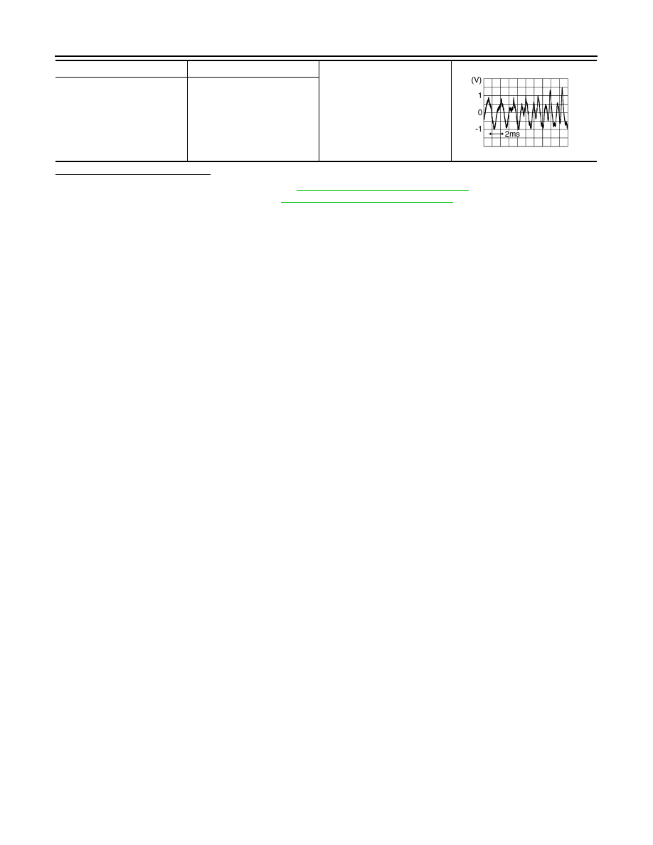
Audio signal output
13
14
SKIB3609E