Nissan Versa Note. Manual - part 41
AV-156
< ECU DIAGNOSIS INFORMATION >
[NAVIGATION]
AROUND VIEW MONITOR CONTROL UNIT
4
(BR)
Ground Ignition signal
Input
ON
—
Battery voltage
8
(Y/L)
Ground Reverse signal
Input
ON
Selector lever in R (re-
verse) position
Battery voltage
Selector lever in other than
R (reverse) position
0 V
10
(P)
—
CAN (L)
Input/
Output
—
—
—
12
(L)
—
CAN (H)
Input/
Output
—
—
—
23
(Shield)
—
Camera image signal
shield
—
—
—
—
24
(W)
Ground Camera image signal
Output
ON
When camera image dis-
play
25
(L)
Ground Rear camera ground
—
ON
—
0 V
26
(G)
Ground Rear camera power supply
Output
ON
CAMERA selected
or
Shift selector in R (reverse)
position.
6.0 V
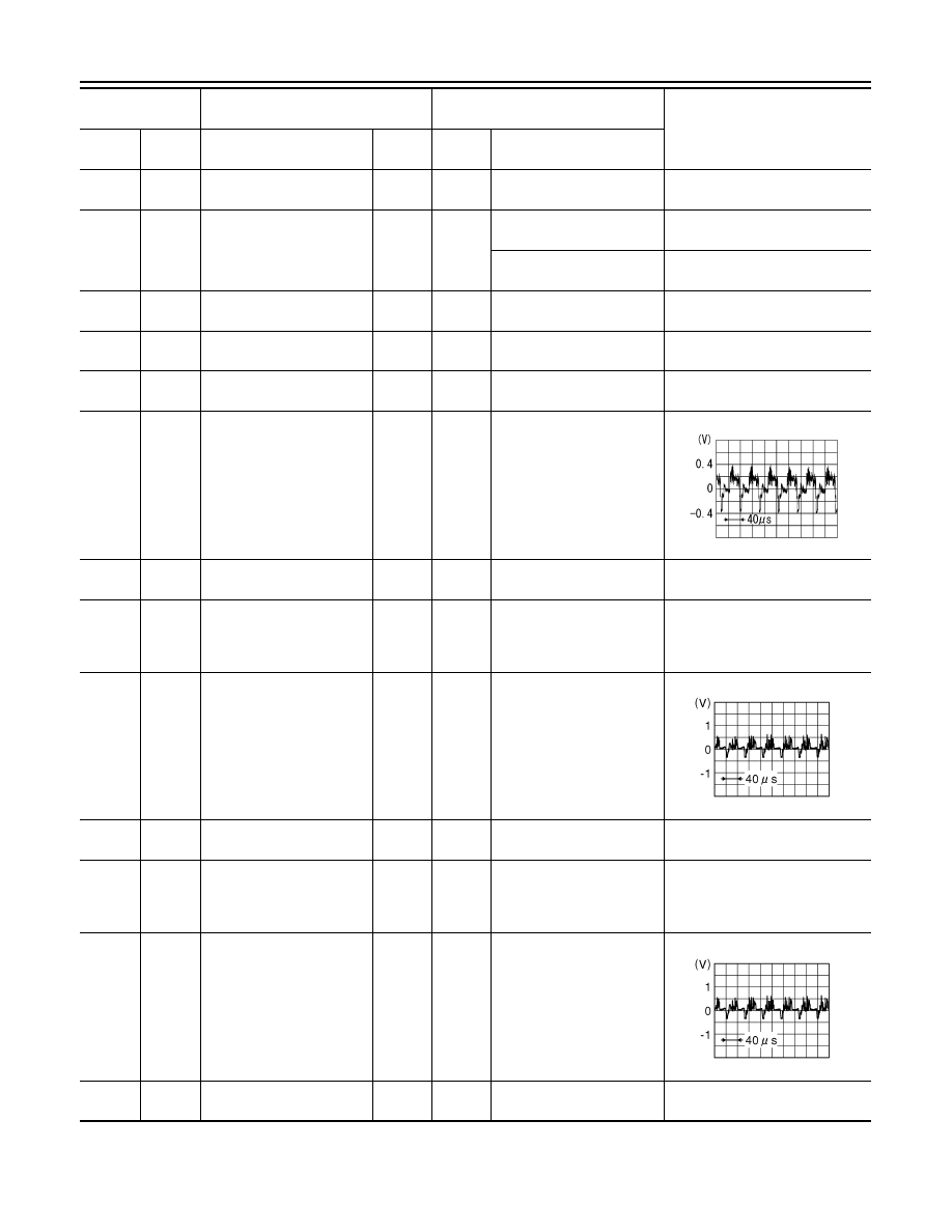
28
(Y)
27
(B)
Rear camera image signal
Input
ON
CAMERA selected
or
Shift selector in R (reverse)
position.
29
(V)
Ground Side camera LH ground
—
ON
—
0 V
30
(R)
Ground
Side camera LH power
supply
Output
ON
CAMERA selected
or
Shift selector in R (reverse)
position.
6.0 V
32
(LG)
31
(Shield)
Side camera LH image sig-
nal
Input
ON
CAMERA selected
or
Shift selector in R (reverse)
position.
33
(B)
Ground Side camera RH ground
—
ON
—
0 V
Terminal
(Wire color)
Description
Condition
Reference value
(Approx.)
+
–
Signal name
Input/
Output
Ignition
switch
Operation
SKIB2251J
JSNIA0834GB
JSNIA0834GB