Index Nissan Nissan Versa Note (2014 year) - Service and Repair Manual
Search
Content .. 8 9 10 11 ..
Nissan Versa Note. Manual - part 10
AV-32
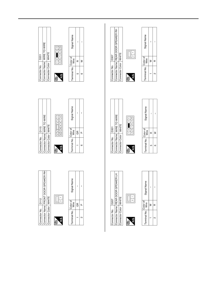
< WIRING DIAGRAM >
[BASE AUDIO]
BASE AUDIO
AANIA1766GB