Nissan Note E12. Manual - part 445


  Index      Nissan     Nissan Note E12 - Service and Repair Manual


Search            


Content   ..  443  444  445  446   ..


Nissan Note E12. Manual - part 445


MA-28

< PERIODIC MAINTENANCE >

CHASSIS AND BODY MAINTENANCE

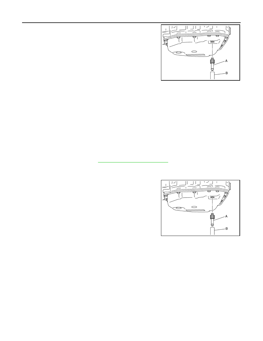
6. Install the charging pipe set (KV311039S0) (A) into the drain

hole.

CAUTION:

Tighten the charging pipe by hand.

7. Install the ATF changer hose (B) to the charging pipe.

CAUTION:

Press the ATF changer hose all the way onto the charging

pipe until it stops.

8. Fill approximately 3 liter (2-5/8 lmp qt) of the CVT fluid. 
9. Remove the ATF changer hose and charging pipe, then install

the drain plug.

NOTE:

Perform this work quickly because CVT fluid leaks. 

10. Lift down the vehicle.
11. Start the engine.
12. While depressing the brake pedal, shift the selector lever to the entire position from “P” to “L”, and shift it

to the “P” position.

NOTE:

Hold the lever at each position for 5 seconds.

13. Check that the CONSULT “Data monitor” in “FLUID TEMP” is 35

°C (95°F) to 45°C (113°F).

14. Stop the engine.
15. Lift up the vehicle.
16. Remove the drain plug, and then drain CVT fluid from oil pan.
17. Repeat steps 6 to 16 (one time).
18. Install the overflow tube. Refer to 

TM-238, "Removal and Installation"

.

CAUTION:

Be sure to tighten to the specified torque. If it is not tightened to the specified torque, the tube may

be damaged.

19. Install the charging pipe set (KV311039S0) (A) into the drain

hole.

CAUTION:

Tighten the charging pipe by hand.

20. Install the ATF changer hose (B) to the charging pipe.

CAUTION:

Press the ATF changer hose all the way onto the charging

pipe until it stops.

21. Fill approximately 3 liter (2-5/8 lmp qt) of the CVT fluid. 
22. Remove the ATF changer hose and charging pipe, then install

the drain plug.

NOTE:

Perform this work quickly because CVT fluid leaks. 

23. Lift down the vehicle.
24. Start the engine.
25. While depressing the brake pedal, shift the selector lever to the entire position from “P” to “L”, and shift it

to the “P” position.

NOTE:

Hold the lever at each position for 5 seconds.

26. Check that the CONSULT “Data monitor” in “FLUID TEMP” is 35

°C (95°F) to 45°C (113°F).

27. Lift up the vehicle.
28. Remove the drain plug and confirm that the CVT fluid is drained from the overflow tube. 

CAUTION:

Perform this work with the vehicle idling.

NOTE:

If the CVT fluid is not drained, refer to “Adjustment” and refill with the CVT fluid. 

JSDIA1876ZZ

JSDIA1876ZZ

CHASSIS AND BODY MAINTENANCE

MA-29

< PERIODIC MAINTENANCE >

C

D

E

F

G

H

I

J

K

L

M

B

MA

N

O

A

29. When the flow of CVT fluid slows to a drip, tighten the drain plug to the specified torque. 

TM-238,

"Removal and Installation"

.

CAUTION:

Never reuse drain plug gasket.

30. Lift down the vehicle.
31. Select “Work Support” in “TRANSMISSION” using CONSULT. 
32. Select “CONFORM CVTF DETERIORTN”.
33. Select “Erase”.
34. Stop the engine.

CVT FLUID : Adjustment

INFOID:0000000009670506

CAUTION:

• Use only Genuine NISSAN CVT Fluid NS-3. Using transmission fluid other than Genuine NISSAN

CVT Fluid NS-3 will damage the CVT, which is not covered by the (NISSAN new vehicle limited) war-

ranty.

• During adjustment of the CVT fluid level, check CONSULT so that the oil temperature may be main-

tained from 35 to 45

°C (95 to 113°F).

• Use caution when looking into the drain hole as there is a risk of dripping fluid entering the eye.
1. Check that the selector lever is in the “P” position, then completely engage the parking brake.
2. Start the engine.
3. Adjust the CVT fluid temperature to be approximately 40

°C (104°F). 

NOTE:

The CVT fluid is largely affected by temperature. Therefore be sure to use CONSULT and check the

“FLUID TEMP” under “TRANSMISSION” in “Data Monitor” while adjusting.

4. While depressing the brake pedal, shift the selector lever to the entire position from “P” to “L”, and shift it

to the “P” position.

NOTE:

Hold the lever at each position for 5 seconds.

5. Lift up the vehicle.
6. Check that there is no CVT fluid leakage.
7. Remove the drain plug. Refer to 

TM-238, "Removal and Installation"

.

8. Install the charging pipe set (KV311039S0) (A) into the drain

plug hole.

CAUTION:

Tighten the charging pipe by hand.

9. Install the ATF changer hose (B) to the charging pipe.

CAUTION:

Press the ATF changer hose all the way onto the charging

pipe until it stops.

10. Fill approximately 0.5 liter (1/2 lmp qt) of the CVT fluid. 
11. Remove the ATF changer hose from the charging pipe, and

check that the CVT fluid drains out from the charging pipe. If it

does not drain out, perform charging again.

CAUTION:

Perform this work with the vehicle idling.

12. When the flow of CVT fluid slows to a drip, remove the charging pipe from the oil pan. 
13. Tighten the drain plug to the specified torque. Refer to 

TM-238, "Removal and Installation"

.

CAUTION:

Never reuse drain plug gasket.

14. Lift down the vehicle.
15. Stop the engine.

CVT fluid

: Refer to 

TM-254, "General Specification"

.

Fluid capacity

: Refer to 

TM-254, "General Specification"

.

JSDIA1876ZZ

MA-30

< PERIODIC MAINTENANCE >

CHASSIS AND BODY MAINTENANCE

CLUTCH FLUID
CLUTCH FLUID : Inspection

INFOID:0000000009670507

CLUTCH FLUID LEAKS

• Check clutch line for cracks, deterioration or other damage. Replace any damaged parts.

• Check for clutch fluid leaks by fully depressing clutch pedal while engine is running.

CAUTION:

If leaks occur around connections, reinstall the lines or replace damaged parts, if necessary.

CLUTCH FLUID LEVEL

• Check that the clutch fluid level in the reservoir tank is within the

specified range, between the MAX and MIN lines as shown.

• Visually check for any clutch fluid leaks around the reservoir tank.

• Check the clutch system for any leaks if the clutch fluid level is

extremely low (lower than MIN).

CLUTCH FLUID : Draining

INFOID:0000000009670508

CAUTION:

Do not spill clutch fluid onto painted surfaces. If clutch fluid spills, wipe up immediately and wash the

affected area with water.
1. Connect a transparent vinyl hose to air bleeder of bleeding con-

nector (1).

2. Press the lock pin (1) into the bleeding connector (2), and main-

tain the position.

JPFIA0007ZZ

JPDIB0144ZZ

PCIB1495E

CHASSIS AND BODY MAINTENANCE

MA-31

< PERIODIC MAINTENANCE >

C

D

E

F

G

H

I

J

K

L

M

B

MA

N

O

A

3. Slide clutch tube (1) for the specified distance (A) in the direction

of the arrow (

) as shown.

CAUTION:

Do not allow the clutch tube to disconnect from the bleed-

ing connector.

4. Depress clutch pedal to gradually discharge clutch fluid.

CAUTION:

Clutch tube is under hydraulic pressure; do not allow the clutch tube to disconnect from the

bleeding connector.

CLUTCH FLUID : Refilling

INFOID:0000000009670509

CAUTION:

Do not spill clutch fluid onto painted surfaces. If clutch fluid spills, wipe up immediately and wash the

affected area with water.
1. Check that there is no foreign material in reservoir tank and then fill with new clutch fluid.

CAUTION:

Do not reuse drained clutch fluid.

2. Connect a transparent vinyl hose to air bleeder of bleeding con-

nector (1).

3. Press the lock pin (1) into the bleeding connector (2), and main-

tain the position.

(2)

: Bleeding connector

Dimension (A)

: 5 mm (0.20 in)

JPDIB0147ZZ

JPDIB0144ZZ

PCIB1495E


Content   ..  443  444  445  446   ..