Nissan Rogue. Manual - part 938


  Index      Nissan     Nissan Rogue (2015 year) - Service and Repair Manual


Search            


Content   ..  936  937  938  939   ..


Nissan Rogue. Manual - part 938


PARKING BRAKE SHOE

PB-13

< REMOVAL AND INSTALLATION >

C

D

E

G

H

I

J

K

L

M

A

B

PB

N

O

P

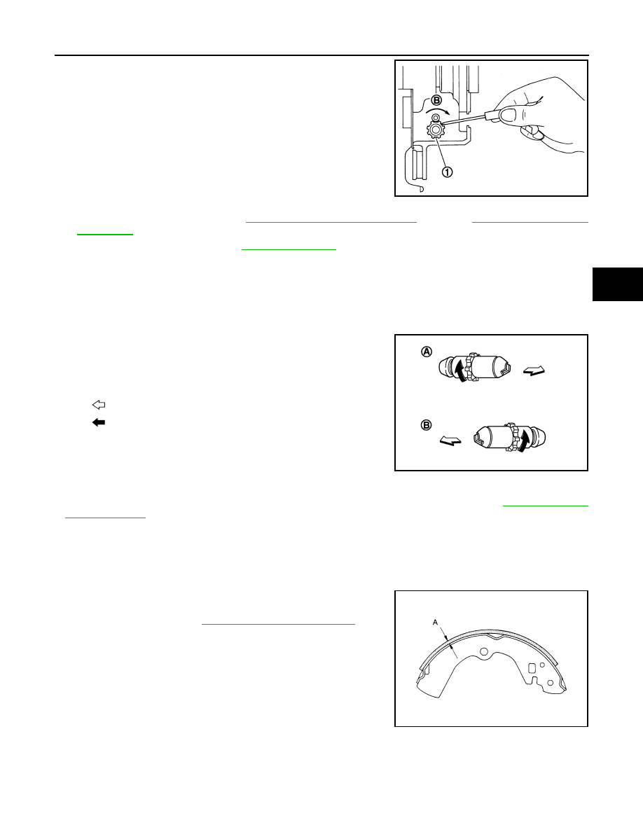
b. Using suitable tool, rotate adjuster (1) in direction (B) to retract

and loosen parking brake shoe.

5. Remove anti-rattle pins, springs, and return springs.

CAUTION:

Do not drop the removed parts.

6. Remove brake strut, adjuster, parking brake shoes and toggle

lever.

CAUTION:

• The leading parking brake shoes are made of different

materials than the trailing parking brake shoes. Do not

misidentify them when removing.

• Do not drop the removed parts.

7. Remove the back plate. Refer to 

RAX-7, "Removal and Installation"

 (FWD) or 

RAX-16, "Removal and

Installation"

 (AWD).

8. Inspect the components. Refer to 

PB-13, "Inspection"

.

INSTALLATION

Installation is in the reverse order of the removal.

• Apply PBC (Poly Butyl Cuprysil) grease or silicone-based grease to the back plate and brake shoe.

CAUTION:

The leading parking brake shoes are made of different materials than the trailing parking brake

shoes. Do not misidentify them when installing.

• Assemble adjusters so that threaded part is expanded when rotat-

ing it in the direction shown by arrow.

• Shorten adjuster by rotating it.

• When assembling, apply PBC (Poly Butyl Cuprysil) grease or sili-

cone-based grease to threads.

• Check parking brake shoe lining surface and drum inner surface

for grease. Wipe off any grease on the surfaces.

• Inspect the parking brake system. Adjust the parking brake system if necessary. Refer to 

PB-4, "Inspection

and Adjustment"

.

Inspection

INFOID:0000000011280112

INSPECTION AFTER REMOVAL

Brake Lining Thickness Inspection

• Check thickness (A) of brake lining.

Drum Inner Diameter Inspection

JPFIB0015ZZ

A: For RH brake
B: For LH brake

: Vehicle front

: Adjuster expands

JPFIB0016ZZ

Limit (A)

: Refer to 

PB-15, "Parking Drum Brake"

.

SBR021A

PB-14

< REMOVAL AND INSTALLATION >

PARKING BRAKE SHOE

• Check inner diameter (B) of drum using suitable tool. 

Other Inspections

• Check brake lining for excessive wear, damage, and peeling. Replace if necessary.

• Check parking brake shoe for excessive wear and damage. Replace if necessary.

• Check anti-rattle pin for excessive wear, damage and rust. Replace if necessary.

• Check adjuster spring, anti-rattle spring and return springs for settling, excessive wear, damage, and rust.

Replace if necessary.

• Check brake strut for excessive wear, damage and rust. Replace if necessary.

• Check toggle lever for excessive wear, damage and rust. Replace if necessary.

• Visually check inside of the drum for rust, cracks, damage or excessive wear with a suitable tool. Replace if

necessary.

Limit (B)

Refer to 

PB-15, "Parking Drum Brake"

.

JPFIB0008ZZ

SERVICE DATA AND SPECIFICATIONS (SDS)

PB-15

< SERVICE DATA AND SPECIFICATIONS (SDS) 

C

D

E

G

H

I

J

K

L

M

A

B

PB

N

O

P

SERVICE DATA AND SPECIFICATIONS (SDS)

SERVICE DATA AND SPECIFICATIONS (SDS)

Parking Drum Brake

INFOID:0000000011280113

Unit: mm (in)

Parking Brake Control

INFOID:0000000011280114

Item

Limit

Brake lining

Thickness

3.2 (0.126)

Wear thickness

 1.5 (0.059)

Drum

Inner diameter 

 172 (6.77)

Wear limit of inner diameter

 173 (6.81)

VIN

Item

Standard

USA Production

Number of notches [under force of 196 N (20.0 kg-f, 44.1 lb-f)]

4 – 5 notches

Number of notches when brake warning lamp turns ON

1 notch

Korea Production

Number of notches [under force of 196 N (20.0 kg-f, 44.1 lb-f)]

6 – 7 notches

Number of notches when brake warning lamp turns ON

1 notch

PCS

PCS-1

ELECTRICAL & POWER CONTROL

C

D

E

F

G

H

I

J

K

L

B

SECTION 

PCS

A

O

P

N

CONTENTS

POWER CONTROL SYSTEM

IPDM E/R

PRECAUTION ...............................................

4

PRECAUTIONS ...................................................

4

Precaution for Supplemental Restraint System 
(SRS) "AIR BAG" and "SEAT BELT PRE-TEN-
SIONER" .................................................................
..

4

Precaution for Work  ..................................................

4

PREPARATION ............................................

5

PREPARATION ...................................................

5

Special Service Tool  .................................................

5

SYSTEM DESCRIPTION  ..............................

6

COMPONENT PARTS  ........................................

6

Component Parts Location ........................................

6

SYSTEM ..............................................................

7

RELAY CONTROL SYSTEM  ......................................

7

RELAY CONTROL SYSTEM : System Descrip-
tion ..........................................................................
..

7

RELAY CONTROL SYSTEM : Fail-safe  ...................

8

SMART FIELD-EFFECT TRANSISTOR (FET)  ...........

9

SMART FIELD-EFFECT TRANSISTOR (FET) : 
System Description  .................................................
..

9

POWER CONSUMPTION CONTROL SYSTEM  .........

9

POWER CONSUMPTION CONTROL SYSTEM : 
System Description  .................................................
..

9

DIAGNOSIS SYSTEM (IPDM E/R) .....................

11

CONSULT Function (IPDM E/R) .............................

11

ECU DIAGNOSIS INFORMATION  ..............

14

IPDM E/R (INTELLIGENT POWER DISTRI-
BUTION MODULE ENGINE ROOM)  .................

14

Reference Value  .....................................................

14

Fail-safe ...................................................................

21

DTC Index ...............................................................

22

WIRING DIAGRAM ......................................

25

IPDM E/R (INTELLIGENT POWER DISTRI-
BUTION MODULE ENGINE ROOM)  ................

25

Wiring Diagram ........................................................

25

BASIC INSPECTION  ...................................

32

ADDITIONAL SERVICE WHEN REPLACING 
IPDM E/R ...........................................................

32

Description ...............................................................

32

Work Procedure .......................................................

32

CONFIGURATION (IPDM E/R)  .........................

33

Description ...............................................................

33

Work Procedure .......................................................

33

Configuration list ......................................................

33

DTC/CIRCUIT DIAGNOSIS  .........................

35

U1000 CAN COMM CIRCUIT  ...........................

35

Description ...............................................................

35

DTC Logic ................................................................

35

Diagnosis Procedure  ...............................................

35

B120E IPDM E/R ...............................................

36

DTC Logic ................................................................

36

Diagnosis Procedure  ...............................................

36

B20DD IGNITION RELAY ON CIRCUIT ...........

37

DTC Logic ................................................................

37

Diagnosis Procedure  ...............................................

37

B20DE IGNITION RELAY OFF CIRCUIT  .........

38

DTC Logic ................................................................

38

Diagnosis Procedure  ...............................................

38

POWER SUPPLY AND GROUND CIRCUIT  ....

39

Diagnosis Procedure  ...............................................

39


Content   ..  936  937  938  939   ..