Nissan Rogue. Manual - part 860
LAN
AVM BRANCH LINE CIRCUIT
LAN-139
< DTC/CIRCUIT DIAGNOSIS >
[CAN SYSTEM (TYPE 3)]
C
D
E
F
G
H
I
J
K
L
B
A
O
P
N
AVM BRANCH LINE CIRCUIT
Diagnosis Procedure
INFOID:0000000011506731
1.
CHECK CONNECTOR
1. Turn the ignition switch OFF.
2. Disconnect the battery cable from the negative terminal.
3. Check the following terminals and connectors for damage, bend and loose connection (unit side and con-
nector side).
-
Around view monitor control unit
-
BCM
Is the inspection result normal?
YES
>> GO TO 2.
NO
>> Repair the terminal and connector.
2.
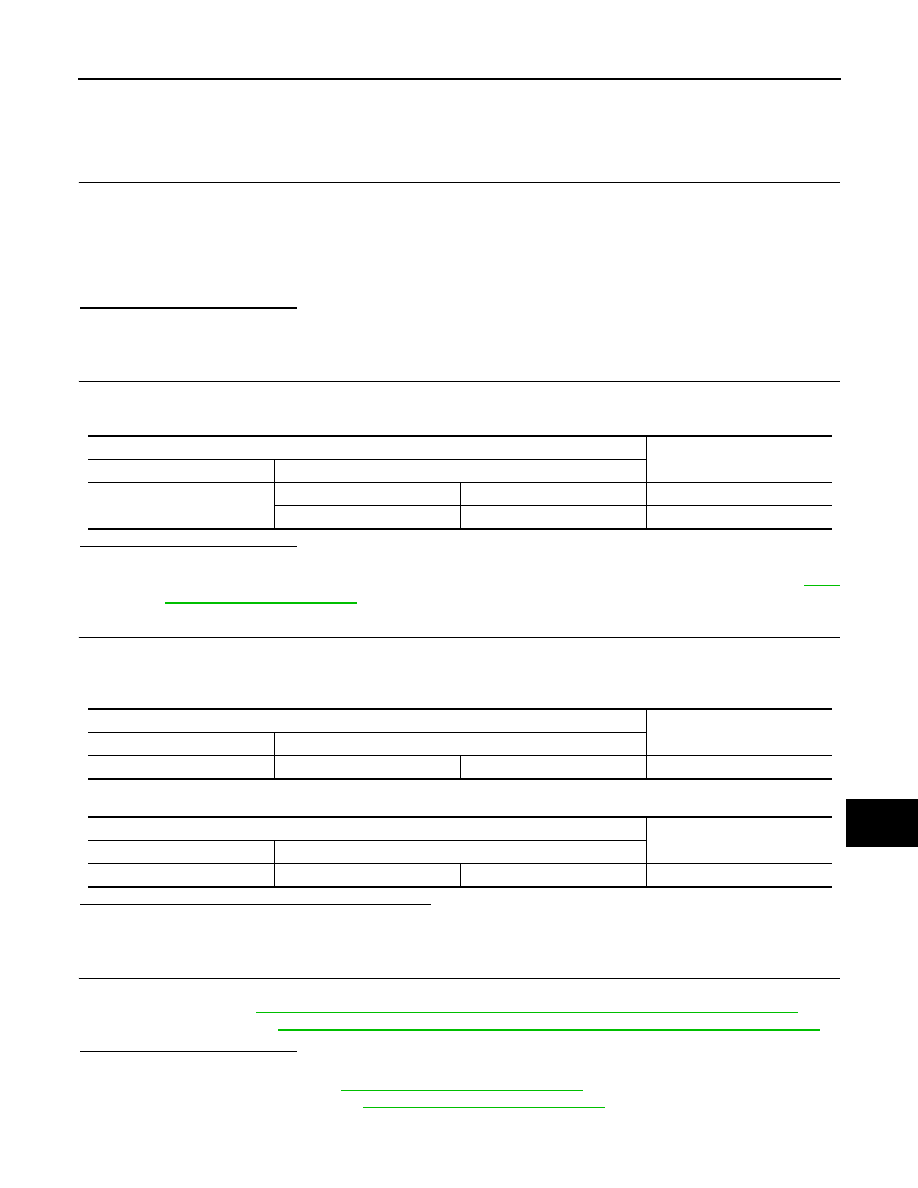
CHECK HARNESS CONTINUITY (OPEN CIRCUIT)
1. Disconnect the connector of BCM.
2. Check the continuity between the BCM harness connector terminals.
Is the inspection result normal?
YES
>> GO TO 3.
NO
>> Check the harness and repair the root cause (CAN communication circuit 2 side). Refer to
.
3.
CHECK HARNESS FOR OPEN CIRCUIT
1. Disconnect the connector of around view monitor control unit.
2. Check the resistance between the around view monitor control unit harness connector terminals.
-
With lane departure prevention system
-
Without lane departure prevention system
Is the measurement value within the specification?
YES
>> GO TO 4.
NO
>> Repair the around view monitor control unit branch line.
4.
CHECK POWER SUPPLY AND GROUND CIRCUIT
Check the power supply and the ground circuit of the around view monitor control unit. Refer to the following.
• Navigation with BOSE:
AV-331, "AROUND VIEW MONITOR CONTROL UNIT : Diagnosis Procedure"
• Navigation without BOSE:
AV-172, "AROUND VIEW MONITOR CONTROL UNIT : Diagnosis Procedure"
Is the inspection result normal?
YES (Present error)>>Replace the around view monitor control unit. Refer to the following.
• Navigation with BOSE:
AV-380, "Removal and Installation"
• Navigation without BOSE:
AV-208, "Removal and Installation"
YES (Past error)>>Error was detected in the around view monitor control unit branch line.
NO
>> Repair the power supply and the ground circuit.
BCM harness connector
Continuity
Connector No.
Terminal No.
M18
6
8
Existed
5
9
Existed
Around view monitor control unit harness connector
Resistance (
Ω)
Connector No.
Terminal No.
M113
27
28
Approx. 54 – 66
Around view monitor control unit harness connector
Resistance (
Ω)
Connector No.
Terminal No.
M103
12
10
Approx. 54 – 66