Nissan Rogue. Manual - part 829


  Index      Nissan     Nissan Rogue (2015 year) - Service and Repair Manual


Search            


Content   ..  827  828  829  830   ..


Nissan Rogue. Manual - part 829


LAN

TROUBLE DIAGNOSIS

LAN-15

< SYSTEM DESCRIPTION >

[CAN FUNDAMENTAL]

C

D

E

F

G

H

I

J

K

L

B

A

O

P

N

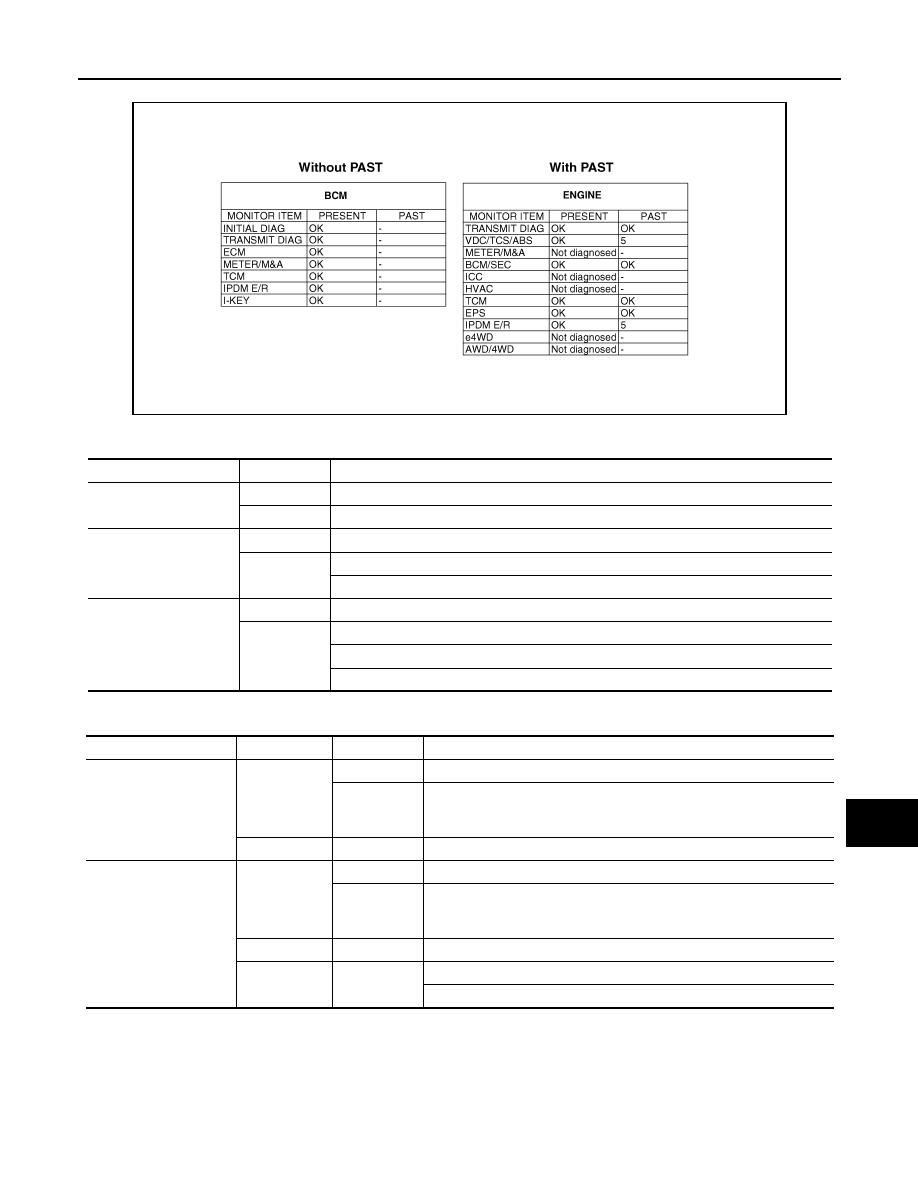
Example: CAN DIAG SUPPORT MNTR indication

Without PAST

With PAST

MONITOR ITEM (ON-BOARD DIAGNOSIS)

NOTE:

For some models, CAN communication diagnosis result is received from the vehicle monitor.

JSMIA0964GB

Item

PRESENT

Description

Initial diagnosis

OK

Normal at present

NG

Control unit error (Except for some control units)

Transmission diagnosis

OK

Normal at present

UNKWN

Unable to transmit signals for 2 seconds or more.

Diagnosis not performed

Control unit name

(Reception diagnosis)

OK

Normal at present

UNKWN

Unable to receive signals for 2 seconds or more.

Diagnosis not performed

No control unit for receiving signals. (No applicable optional parts)

Item

PRESENT

PAST

Description

Transmission diagnosis

OK

OK

Normal at present and in the past

1 – 39

Normal at present, but unable to transmit signals for 2 seconds or more 
in the past. (The number indicates the number of ignition switch cycles 
from OFF to ON.)

UNKWN

0

Unable to transmit signals for 2 seconds or more at present.

Control unit name

(Reception diagnosis)

OK

OK

Normal at present and in the past

1 – 39

Normal at present, but unable to receive signals for 2 seconds or more 
in the past. (The number indicates the number of ignition switch cycles 
from OFF to ON.)

UNKWN

0

Unable to receive signals for 2 seconds or more at present.

Not diagnosed

Diagnosis not performed.

No control unit for receiving signals. (No applicable optional parts)

LAN-16

< SYSTEM DESCRIPTION >

[CAN FUNDAMENTAL]

TROUBLE DIAGNOSIS

Example: Vehicle Display 

How to Use CAN Communication Signal Chart

INFOID:0000000011277508

The CAN communication signal chart lists the signals needed for trouble diagnosis. It is useful for detecting

the root cause by finding a signal related to the symptom, and by checking transmission and reception unit.

Item

Result indi-

cated

Error counter

Description

CAN_COMM

(Initial diagnosis)

OK

0

Normal at present

NG

1 – 50

Control unit error
(The number indicates how many times diagnosis has been 
run.)

CAN_CIRC_1

(Transmission diagnosis)

OK

0

Normal at present

UNKWN

1 – 50

Unable to transmit for 2 seconds or more at present.
(The number indicates how many times diagnosis has been 
run.)

CAN_CIRC_2 – 9

(Reception diagnosis of each unit)

OK

0

Normal at present

UNKWN

1 – 50

Unable to transmit for 2 seconds or more at present.
(The number indicates how many times diagnosis has been 
run.)

Diagnosis not performed.

No control unit for receiving signals. (No applicable optional 
parts)

SKIB8715E

LAN

DIAGNOSIS AND REPAIR WORKFLOW

LAN-17

< BASIC INSPECTION >

[CAN FUNDAMENTAL]

C

D

E

F

G

H

I

J

K

L

B

A

O

P

N

BASIC INSPECTION

DIAGNOSIS AND REPAIR WORKFLOW

Trouble Diagnosis Flow Chart

INFOID:0000000011277509

DESCRIPTION

DETAIL OF TROUBLE DIAGNOSIS FLOW CHART

1.

INTERVIEW WITH CUSTOMER

Interview with the customer is important to detect the root cause of CAN communication system errors and to

understand vehicle condition and symptoms for proper trouble diagnosis.

Points in interview

• What: Parts name, system name

• When: Date, Frequency

• Where: Road condition, Place

• In what condition: Driving condition/environment

• Result: Symptom

Notes for checking error symptoms:

• Check normal units as well as error symptoms.

- Example: Circuit between ECM and the combination meter is judged normal if the customer indicates

tachometer functions normally.

JSMIA0528GB

LAN-18

< BASIC INSPECTION >

[CAN FUNDAMENTAL]

DIAGNOSIS AND REPAIR WORKFLOW

• When a CAN communication system error is present, multiple control units may malfunction or go into fail-

safe mode.

• Indication of the combination meter is important to detect the root cause because it is the most obvious to

the customer, and it performs CAN communication with many units.

>> GO TO 2.

2.

INSPECTION OF VEHICLE CONDITION

Check whether the symptom is reproduced or not.

NOTE:

Do not turn the ignition switch OFF or disconnect the 12V battery cable while reproducing the error. The error

may temporarily correct itself, making it difficult to determine the root cause.

>> GO TO 3.

3.

CHECK OF CAN SYSTEM TYPE (HOW TO USE CAN SYSTEM TYPE SPECIFICATION CHART)

Determine CAN system type based on vehicle equipment.

NOTE:

• This chart is used if CONSULT does not automatically recognize CAN system type.

• There are two styles for CAN system type specification charts. Depending on the number of available sys-

tem types, either style A or style B may be used.

• CAN System Type Specification Chart (Style A)

NOTE:

SKIB8717E


Content   ..  827  828  829  830   ..