Nissan Rogue. Manual - part 806


  Index      Nissan     Nissan Rogue (2015 year) - Service and Repair Manual


Search            


Content   ..  804  805  806  807   ..


Nissan Rogue. Manual - part 806


LUGGAGE ROOM LAMP CIRCUIT

INL-51

< DTC/CIRCUIT DIAGNOSIS >

C

D

E

F

G

H

I

J

K

M

A

B

INL

N

O

P

LUGGAGE ROOM LAMP CIRCUIT

Description

INFOID:0000000011279216

Controls the luggage room lamp (ground side) to turn the luggage room lamp ON and OFF.

Diagnosis Procedure

INFOID:0000000011279217

CAUTION:

 Before performing the diagnosis, check that the following is normal:

• Interior room lamp power supply

• Luggage room lamp bulb

1.

CHECK LUGGAGE ROOM LAMP OUTPUT

1. Turn ignition switch OFF.

2. Remove the luggage room lamp bulb.

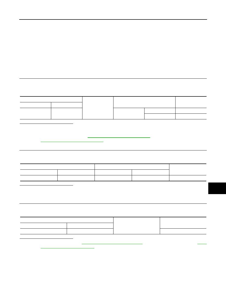
3. Check continuity between BCM harness connector and ground.

Is the inspection result normal?

YES

>> GO TO 2.

Fixed ON>>GO TO 3.

Fixed OFF>>Replace BCM. Refer to 

BCS-75, "Removal and Installation"

 (with Intelligent Key system) or

BCS-135, "Removal and Installation"

 (without Intelligent Key system).

2.

CHECK LUGGAGE ROOM LAMP OPEN CIRCUIT

1. Disconnect BCM connector.

2. Check continuity between BCM harness connector and luggage room lamp harness connector.

Is the inspection result normal?

YES

>> Replace luggage room lamp.

NO

>> Repair or replace harnesses.

3.

CHECK LUGGAGE ROOM LAMP SHORT CIRCUIT

1. Disconnect BCM connector.

2. Check continuity between BCM harness connector and ground.

Is the inspection result normal?

YES

>> Replace BCM. Refer to 

BCS-75, "Removal and Installation"

 (with Intelligent Key system) or 

BCS-

135, "Removal and Installation"

 (without Intelligent Key system).

NO

>> Repair or replace harnesses.

BCM

Ground

Condition

Continuity

Connector

Terminal

B23

151

Back door

Open

Yes

Closed

No

BCM

Luggage room lamp

Continuity

Connector

Terminal

Connector

Terminal

B23

151

B118

2

Yes

BCM

Ground

Continuity

Connector

Terminal

B23

151

No

INL-52

< DTC/CIRCUIT DIAGNOSIS >

PUSH-BUTTON IGNITION SWITCH ILLUMINATION CIRCUIT

PUSH-BUTTON IGNITION SWITCH ILLUMINATION CIRCUIT

Description

INFOID:0000000011279218

Provides the power supply and the ground to control the push button ignition switch illumination.

Component Function Check

INFOID:0000000011279219

1.

CHECK PUSH BUTTON IGNITION SWITCH ILLUMINATION OPERATION

CONSULT ACTIVE TEST

1. Turn the ignition switch ON.

2. Select “ENGINE SW ILLUMI” in “Active Test” of “BCM”.

3. With operating the test items, check that the push button ignition switch illumination turns ON/OFF.

Does the push button ignition switch illumination turn ON/OFF?

YES

>> Ignition switch illumination circuit is normal.

NO

>> Refer to 

INL-52, "Diagnosis Procedure"

.

Diagnosis Procedure

INFOID:0000000011279220

1.

CHECK PUSH BUTTON IGNITION SWITCH ILLUMINATION POWER SUPPLY OUTPUT

1. Turn ignition switch OFF.

2. Disconnect ignition switch connector.

3. Check voltage between ignition switch harness connector and ground.

Is the inspection result normal?

YES

>> GO TO 4.

NO

>> GO TO 2.

2.

CHECK PUSH BUTTON IGNITION SWITCH ILLUMINATION POWER SUPPLY OPEN CIRCUIT

1. Turn the ignition switch OFF.

2. Disconnect BCM connector.

3. Check continuity between BCM harness connector and the ignition switch harness connector.

Is the inspection result normal?

YES

>> GO TO 3.

NO

>> Repair or replace harnesses.

3.

CHECK PUSH BUTTON IGNITION SWITCH ILLUMINATION POWER SUPPLY SHORT CIRCUIT

Check continuity between BCM harness connector and ground.

On

: Push button ignition switch illumination ON

Off

: Push button ignition switch illumination OFF

(+)

(–)

Condition

Voltage

(Approx.)

 Ignition switch

Connector

Terminal

M17

8

Ground

Push button ignition switch il-
lumination

ON

Battery voltage

OFF

0 V

BCM

Ignition switch

Continuity

Connector

Terminal

Connector

Terminal

M19

88

M17

8

Yes

BCM

Ground

Continuity

Connector

Terminal

M19

88

No

PUSH-BUTTON IGNITION SWITCH ILLUMINATION CIRCUIT

INL-53

< DTC/CIRCUIT DIAGNOSIS >

C

D

E

F

G

H

I

J

K

M

A

B

INL

N

O

P

Is the inspection result normal?

YES

>> Replace BCM. Refer to 

BCS-75, "Removal and Installation"

 (with Intelligent Key system) or 

BCS-

135, "Removal and Installation"

 (without Intelligent Key system).

NO

>> Repair or replace harnesses.

4.

CHECK PUSH BUTTON IGNITION SWITCH ILLUMINATION GROUND CIRCUIT

1. Turn the ignition switch OFF.

2. Check continuity between ignition switch harness connector and ground.

Is the inspection result normal?

YES

>> Replace ignition switch. Refer to 

SEC-117, "Removal and Installation"

.

NO

>> Repair or replace harnesses.

Ignition switch

Ground

Continuity

Connector

Terminal

M17

7

Yes

INL-54

< SYMPTOM DIAGNOSIS >

INTERIOR LIGHTING SYSTEM SYMPTOMS

SYMPTOM DIAGNOSIS

INTERIOR LIGHTING SYSTEM SYMPTOMS

Symptom Table

INFOID:0000000011279221

CAUTION:

Perform the “Self Diagnostic Result” with CONSULT before the symptom diagnosis. Perform the trou-

ble diagnosis if any DTC is detected.

Symptom

Possible cause

Inspection item

All the following lamps do not turn ON:
• Map  lamp  assembly
• Room  lamp
• Luggage room lamp

• Harness between BCM and each 

interior room lamp

• BCM

Interior room lamp power supply cir-
cuit
Refer to 

INL-46

.

• Interior room lamp does not turn ON even 

though the door is open.
(It turns ON when turning the interior room 
lamp ON.)

• Interior room lamp does not turn OFF even 

though the door is closed.

• Harness between BCM and each 

door switch

• Harness between BCM and each 

interior room lamp

• BCM

Door switch circuit
Refer to 

DLK-156, 

"Component Function Check"

 (with 

Intelligent Key system) or 

DLK-330, 

"Component Function Check"

 (with-

out Intelligent Key system).

Interior room lamp control circuit
Refer to 

INL-49

.

Interior room lamp timer does not activate.
(It turns ON/ OFF when the door opens/closes.)

Check the interior room lamp setting.
Refer to 

INL-9, "INTERIOR ROOM 

LAMP BATTERY SAVER SYSTEM : 
System Description"

.

•  Luggage room lamp does not turn ON even 

though the back door is open.

• Luggage room lamp does not turn OFF even 

though the back door is closed.

• Harness between BCM and back 

door switch

• Harness between BCM and lug-

gage room lamp

• BCM

Back door switch circuit
Refer to 

DLK-158, 

"Component Function Check"

 (with 

Intelligent Key system) or 

DLK-330, 

"Component Function Check"

 (with-

out Intelligent Key system).

Luggage room lamp circuit
Refer to 

INL-51

.

Ignition switch illumination does not illuminate.

• Harness between BCM and Igni-

tion switch

• BCM

Ignition switch illumination circuit
Refer to 

INL-52

.

Interior room lamp battery saver does not acti-
vate.

BCM

Replace BCM.
Refer to 

BCS-75, "Removal and In-

stallation"

 (with Intelligent Key sys-

tem) or 

BCS-135, "Removal and 

Installation"

 (without Intelligent Key 

system).


Content   ..  804  805  806  807   ..