Nissan Rogue. Manual - part 804
DIAGNOSIS AND REPAIR WORKFLOW
INL-43
< BASIC INSPECTION >
C
D
E
F
G
H
I
J
K
M
A
B
INL
N
O
P
BASIC INSPECTION
DIAGNOSIS AND REPAIR WORKFLOW
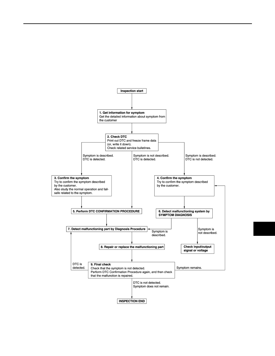
Work Flow
INFOID:0000000011279209
OVERALL SEQUENCE
DETAILED FLOW
JMKIA8652GB
|
|
|
DIAGNOSIS AND REPAIR WORKFLOW INL-43 < BASIC INSPECTION > C D E F G H I J K M A B INL N O P BASIC INSPECTION DIAGNOSIS AND REPAIR WORKFLOW Work Flow INFOID:0000000011279209 OVERALL SEQUENCE DETAILED FLOW JMKIA8652GB |