Nissan Rogue. Manual - part 752
HAC-30
< ECU DIAGNOSIS INFORMATION >
[AUTOMATIC AIR CONDITIONING]
A/C AUTO AMP.
Terminal No.
(Wire color)
Description
Condition
Value
(Approx.)
+
−
Signal name
Input/
Output
1
(SB)
3
(B)
Ignition power supply
Input
Ignition switch ON
Battery voltage
3
(B)
Ground
Ground
—
Ignition switch ON
0 – 0.1 V
11
(L)
3
(B)
CAN-H
Input/
Output
Ignition switch ON
—
13
(Y)
3
(B)
In-vehicle sensor signal
Input
Ignition switch ON
0 – 4.8 V
Output voltage varies with in-ve-
hicle temperature
14
(G)
3
(B)
Sunload sensor signal
Input
Ignition switch ON
0 – 4.8 V
Output voltage varies with sun-
load amount
23
(BR)
3
(B)
Sensor ground
—
Ignition switch ON
0 – 0.1 V
31
(R)
3
(B)
CAN-L
Input/
Output
Ignition switch ON
—
33
(LG)
3
(B)
LIN
Input/
Output
Ignition switch ON
—
41
(W)
3
(B)
ACTR V
Output
Ignition switch ON
Battery voltage
44
(L)
3
(B)
INTAKE
drive 1
Intake door motor
drive signal
Output
• Ignition switch ON
• Right after the Intake
switch operation
45
(R)
3
(B)
INTAKE
drive 2
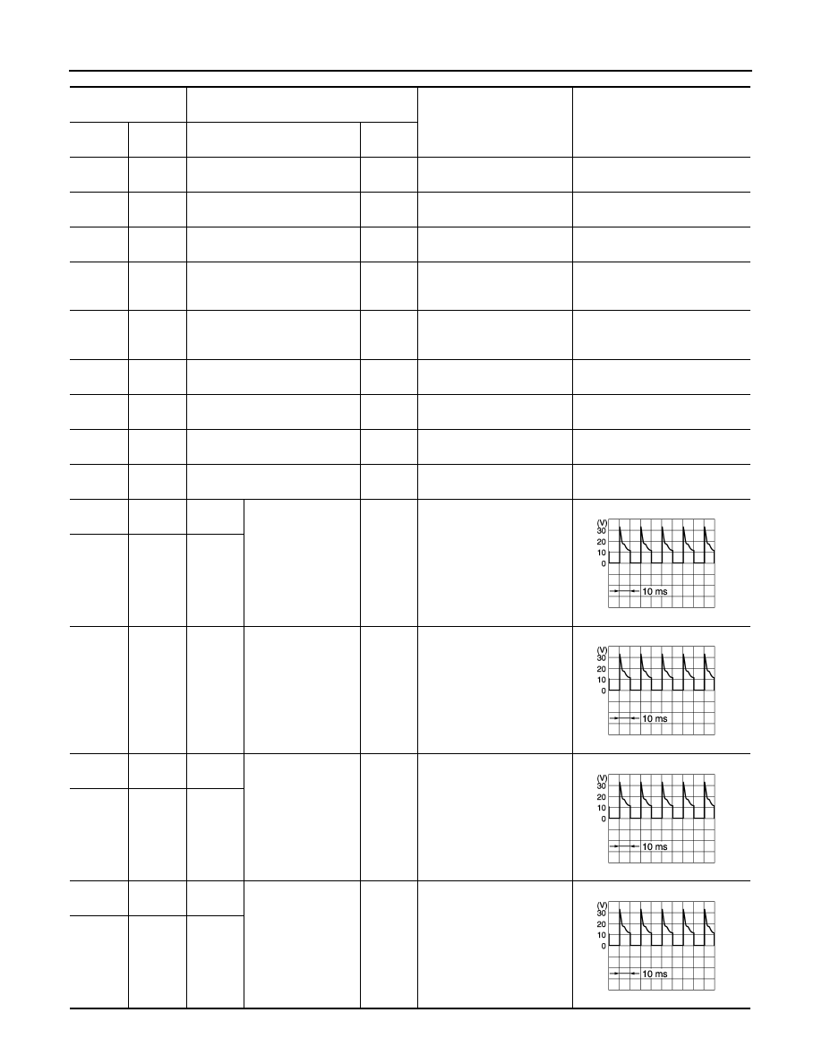
47
(BR)
3
(B)
INTAKE
drive 3
Intake door motor
drive signal
Output
• Ignition switch ON
• Right after the intake
switch operation
49
(L)
3
(B)
MODE
drive 1
Mode door motor
drive signal
Output
• Ignition switch ON
• Right after the MODE
switch operation
50
(BR)
3
(B)
MODE
drive 2
51
(L)
3
(B)
A/MIX
drive 1
Air mix door motor
(driver side) drive
signal
Output
• Ignition switch ON
• Right after the tempera-
ture control switch (driver
side) operation
52
(W)
3
(B)
A/MIX
drive 2
JPIIA1647GB
JPIIA1647GB
JPIIA1647GB
JPIIA1647GB