Nissan Rogue. Manual - part 733


  Index      Nissan     Nissan Rogue (2015 year) - Service and Repair Manual


Search            


Content   ..  731  732  733  734   ..


Nissan Rogue. Manual - part 733


BACK DOOR WINDOW GLASS

GW-29

< REMOVAL AND INSTALLATION >

C

D

E

F

G

H

I

J

L

M

A

B

GW

N

O

P

• Keep heat and open flames away as primers and adhesive are flammable.

• Materials contained in the kit are harmful if swallowed, and may irritate skin and eyes. Avoid contact

with the skin and eyes.

• Use in an open, well ventilated location. Avoid breathing vapors. They can be harmful if inhaled. If

affected by vapor inhalation, immediately move to an area with fresh air.

• Driving vehicle before urethane adhesive has completely cured may affect performance of the wind-

shield in case of an accident.

CAUTION:

• Do not use adhesive which is past its usable term. Shelf life of this product is limited to six months

after date of manufacture. Carefully adhere to expiration or manufacture date printed on box.

• Keep primers and adhesive in cool, dry place. Ideally, they should be stored in refrigerator.

• Do not leave primers or adhesive cartridge unattended with their caps open or off.

• Vehicle should not be driven for at least 24 hours or until urethane adhesive has completely cured.

Curing time varies depending on temperature and humidity. Curing time will increase under lower

temperatures and lower humidity.

REPAIRING WATER LEAKS FOR BACK DOOR GLASS

• Leaks can be repaired without removing and reinstalling glass.

• Determine extent of leak, if water leaks between urethane adhesive material and body or glass.

• This can be done by applying water to glass area while pushing glass outward.

• Apply primer (if necessary) and then urethane adhesive to leak point to stop leak.

Inspection

INFOID:0000000011276526

REPAIRING WATER LEAKAGE FOR BACK DOOR WINDOW GLASS

Leakage can be repaired without removing the glass.

Determine the extent of leakage if water is leaking between the urethane adhesive material and body or glass.

This can be done by applying water to the back door window glass area while pushing glass outward.

Apply primer (if necessary) and then urethane adhesive to the leakage point to stop the leakage.
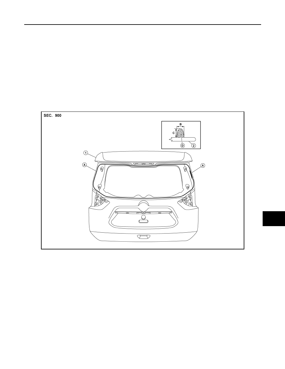
ALKIA3509ZZ

1. Back door

2. Back door window glass

A. Primer and adhesive area

B. 7.0 mm (0.28 in)

C. 12.0 mm (0.47 in)

D. Adhesive

HA-1

VENTILATION, HEATER & AIR CONDITIONER

C

D

E

F

G

H

J

K

L

M

SECTION 

HA

A

B

HA

N

O

P

CONTENTS

HEATER & AIR CONDITIONING SYSTEM

PRECAUTION ...............................................

3

PRECAUTIONS ...................................................

3

Precaution for Supplemental Restraint System 
(SRS) "AIR BAG" and "SEAT BELT PRE-TEN-
SIONER" .................................................................
..

3

Precaution for Work  ..................................................

3

Procedure without Cowl Top Cover .......................

4

Precautions For Refrigerant System Service  ............

4

Service Equipment  ....................................................

6

PREPARATION ............................................

9

PREPARATION ...................................................

9

Special Service Tool  .................................................

9

Commercial Service Tool  ........................................

10

Sealant and/or Oil  ...................................................

11

SYSTEM DESCRIPTION  .............................

12

COMPONENT PARTS  .......................................

12

Component Parts Location ......................................

12

Component Description ...........................................

12

SYSTEM .............................................................

13

System Diagram ......................................................

13

System Description  .................................................

13

BASIC INSPECTION  ...................................

15

DIAGNOSIS AND REPAIR WORKFLOW  .........

15

Workflow .................................................................

15

SYMPTOM DIAGNOSIS  ..............................

17

REFRIGERATION SYSTEM SYMPTOMS .........

17

Trouble Diagnosis For Unusual Pressure  ...............

17

Symptom Table  .......................................................

17

COMPRESSOR SYSTEM SYMPTOMS .............

20

Symptom Table  .......................................................

20

PERIODIC MAINTENANCE .........................

21

REFRIGERANT .................................................

21

Description ...............................................................

21

Leak Test .................................................................

21

Recycle Refrigerant  .................................................

22

Charge Refrigerant  ..................................................

23

OIL .....................................................................

24

Description ...............................................................

24

Inspection ................................................................

24

Perform Oil Return Operation ..................................

24

Oil Adjusting Procedure for Components Replace-
ment Except Compressor  ........................................

24

Oil Adjusting Procedure for Compressor Replace-
ment .........................................................................

25

PERFORMANCE TEST  ....................................

27

Inspection ................................................................

27

REMOVAL AND INSTALLATION ...............

29

COMPRESSOR .................................................

29

Exploded View .........................................................

29

Removal and Installation  .........................................

29

COOLER PIPE AND HOSE  ..............................

31

Exploded View .........................................................

31

LOW-PRESSURE PIPE  .............................................

31

LOW-PRESSURE PIPE : Removal and Installa-
tion ...........................................................................

31

LOW-PRESSURE FLEXIBLE HOSE .........................

33

LOW-PRESSURE FLEXIBLE HOSE : Removal 
and Installation  ........................................................

33

HIGH-PRESSURE PIPE  ............................................

34

HIGH-PRESSURE PIPE : Removal and Installa-
tion ...........................................................................

34

HIGH-PRESSURE FLEXIBLE HOSE  ........................

35

HIGH-PRESSURE FLEXIBLE HOSE : Removal 
and Installation  ........................................................

35

HA-2

CONDENSER ....................................................

37

Exploded View ........................................................

37

CONDENSER ............................................................

37

CONDENSER : Removal and Installation ..............

37

LIQUID TANK ............................................................

38

LIQUID TANK : Removal and Installation ...............

38

REFRIGERANT PRESSURE SENSOR ....................

38

REFRIGERANT PRESSURE SENSOR : Remov-
al and Installation ...................................................
.

38

HEATING AND COOLING UNIT ASSEMBLY ...

39

Exploded View ........................................................

39

HEATING AND COOLING UNIT ASSEMBLY ..........

41

HEATING AND COOLING UNIT ASSEMBLY : 
Removal and Installation  .......................................
.

42

HEATER CORE .........................................................

42

HEATER CORE : Exploded View  ...........................

43

HEATER CORE : Removal and Installation ............

43

EVAPORATOR ..........................................................

43

EVAPORATOR : Exploded View ............................

44

EVAPORATOR : Removal and Installation .............

44

EXPANSION VALVE .................................................

44

EXPANSION VALVE : Removal and Installation  ....

44

SERVICE DATA AND SPECIFICATIONS 
(SDS) ..........................................................

46

SERVICE DATA AND SPECIFICATIONS 
(SDS) .................................................................

46

Compressor ............................................................

46

Oil ............................................................................

46

Refrigerant ..............................................................

46

PRECAUTIONS

HA-3

< PRECAUTION >

C

D

E

F

G

H

J

K

L

M

A

B

HA

N

O

P

PRECAUTION

PRECAUTIONS

Precaution for Supplemental Restraint System (SRS) "AIR BAG" and "SEAT BELT 
PRE-TENSIONER"

INFOID:0000000011279465

The Supplemental Restraint System such as “AIR BAG” and “SEAT BELT PRE-TENSIONER”, used along

with a front seat belt, helps to reduce the risk or severity of injury to the driver and front passenger for certain

types of collision. Information necessary to service the system safely is included in the SR and SB section of

this Service Manual.

WARNING:

• To avoid rendering the SRS inoperative, which could increase the risk of personal injury or death in

the event of a collision which would result in air bag inflation, all maintenance must be performed by

an authorized NISSAN/INFINITI dealer.

• Improper maintenance, including incorrect removal and installation of the SRS, can lead to personal

injury caused by unintentional activation of the system. For removal of Spiral Cable and Air Bag

Module, see the SR section.

• Do not use electrical test equipment on any circuit related to the SRS unless instructed to in this

Service Manual. SRS wiring harnesses can be identified by yellow and/or orange harnesses or har-

ness connectors.

PRECAUTIONS WHEN USING POWER TOOLS (AIR OR ELECTRIC) AND HAMMERS

WARNING:

• When working near the Airbag Diagnosis Sensor Unit or other Airbag System sensors with the Igni-

tion ON or engine running, DO NOT use air or electric power tools or strike near the sensor(s) with a

hammer. Heavy vibration could activate the sensor(s) and deploy the air bag(s), possibly causing

serious injury.

• When using air or electric power tools or hammers, always switch the Ignition OFF, disconnect the

battery and wait at least three minutes before performing any service.

Precaution for Work

INFOID:0000000011279466

• When removing or disassembling each component, be careful not to damage or deform it. If a component

may be subject to interference, be sure to protect it with a shop cloth.

• When removing (disengaging) components with a screwdriver or similar tool, be sure to wrap the component

with a shop cloth or vinyl tape to protect it.

• Protect the removed parts with a shop cloth and prevent them from being dropped.

• Replace a deformed or damaged clip.

• If a part is specified as a non-reusable part, always replace it with a new one.

• Be sure to tighten bolts and nuts securely to the specified torque.

• After installation is complete, be sure to check that each part works properly.

• Follow the steps below to clean components:

- Water soluble dirt:

• Dip a soft cloth into lukewarm water, wring the water out of the cloth and wipe the dirty area.

• Then rub with a soft, dry cloth.

- Oily  dirt:

• Dip a soft cloth into lukewarm water with mild detergent (concentration: within 2 to 3%) and wipe the dirty

area.

• Then dip a cloth into fresh water, wring the water out of the cloth and wipe the detergent off.

• Then rub with a soft, dry cloth.

- Do not use organic solvent such as thinner, benzene, alcohol or gasoline.

- For genuine leather seats, use a genuine leather seat cleaner.


Content   ..  731  732  733  734   ..