Nissan Rogue. Manual - part 725
 

  Index      Nissan     Nissan Rogue (2015 year) - Service and Repair Manual


Search            


Content   ..  723  724  725  726   ..


Nissan Rogue. Manual - part 725


SERVICE INFORMATION FOR ELECTRICAL INCIDENT

GI-51

< BASIC INSPECTION >

C

D

E

F

G

H

I

J

K

L

M

B

GI

N

O

P

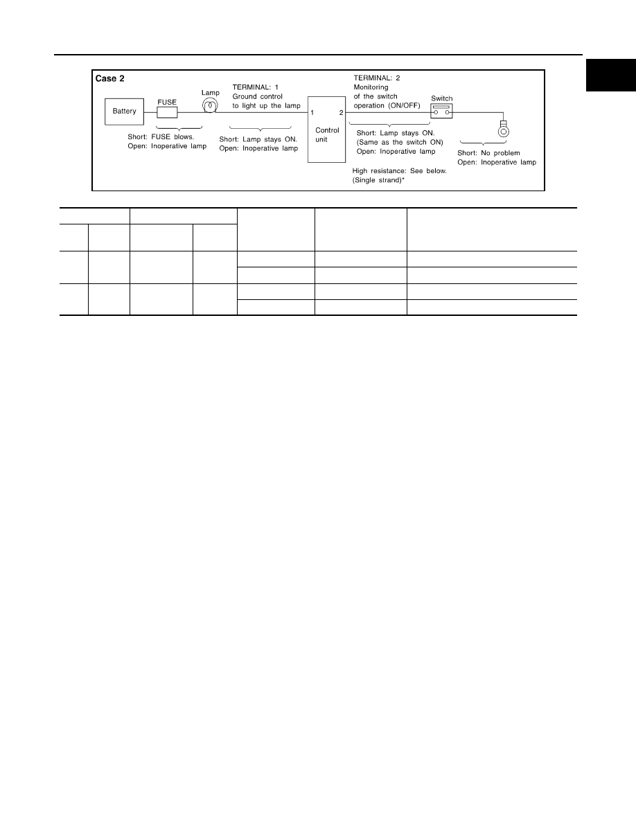
CASE 2

INPUT-OUTPUT VOLTAGE CHART

• The voltage value is based on the body ground.
• *: If high resistance exists in the switch side circuit (caused by a single strand), terminal 2 does not detect approx. 0V. Control unit

does not detect the switch is ON even if the switch does not turn ON. Therefore, the control unit does not control ground to light up the
lamp.

Terminal No.

Description

Condition

Value (Approx.)

In case of high resistance such as single 
strand (V) *

+

Signal name

Input/

Output

1

Body 
ground

Lamp

Output

Switch ON

0V

Battery voltage (Inoperative lamp)

Switch OFF

Battery voltage

Battery voltage

2

Body 
ground

Switch

Input

Switch ON

0 V

Higher than 0 Approx. 4 (Example)

Switch OFF

5 V

Approx. 5

MGI035A

GI-52

< BASIC INSPECTION >

CONSULT/GST CHECKING SYSTEM

CONSULT/GST CHECKING SYSTEM

Description

INFOID:0000000011278281

NOTE:

This vehicle is diagnosed using the CONSULT-III plus.

• When CONSULT is connected with a data link connector equipped

on the vehicle side, it will communicate with the control unit

equipped in the vehicle and then enable various kinds of diagnos-

tic tests.

• Refer to “CONSULT-III plus Operation Manual” for more informa-

tion.

Function and System Application

INFOID:0000000011278282

1

: Hood release handle

2

: Data link connector

ALAIA0109ZZ

Diagnosis (All 

Systems)

Description

ENGINE

ABS

METER/M

&

A

BCM

CAN G

A

TE

W

A

Y

AIR BAG

TRANSMISSION

EPS/

DAST 3

IP

DM E/

R

AV

M

LASER/

R

ADR

1

AIR PRE

SSURE MO

NIT

O

R

ALL MODE 

A

W

D/4W

D

1

CHAS

S

IS CONTROL

HV

AC

A

T

UO B

A

CK DOOR

1

MUL

T

I A

V

OC

CUP

ANT D

E

TECTION

Self Diagnostic 
Result

The ECU self diagnostic results are 
displayed.

x

x

x

x

x

x

x

x

x

x

x

x

x

x

x

x

x

-

Data Monitor

The ECU input/output data is dis-
played in real time.

x

x

x

x

x

x

x

x

x

x

x

x

x

x

x

x

x

-

Work support

The settings for ECU functions can 
be changed.

x

x

x

x

-

-

x

-

x

x

x

x

x

-

x

x

-

x

Active Test

The ECU activates outputs to test 
components.

x

x

-

x

-

-

x

-

x

x

x

x

x

x

x

-

-

-

ECU identifica-
tion

The  ECU  part  number  is  displayed.

x

x

x

x

x

x

x

x

x

x

x

x

x

x

x

x

x

-

DTC Work Sup-
port

The status of system monitoring tests 
and the self diagnosis status/results 
can be confirmed.

x

-

-

-

-

-

-

-

-

-

-

-

-

-

-

-

-

-

Warning History

Displays the history of the combina-
tion meter warning lamp indicators.

-

-

x

-

-

-

-

-

-

-

-

-

-

-

-

-

-

-

TROUBLE DIAG 
RECORD

Self diagnostic history and trouble di-
agnosis records in ECU are dis-
played.

-

-

-

-

-

x

-

-

-

-

-

-

-

-

-

-

-

-

CAN Diag

This mode displays network diagnos-
tic results of CAN communication us-
ing a diagram.

x

x

x

x

x

x

x

x

x

x

x

x

x

x

x

x

x

-

CAN DIAG SUP-
PORT MNTR

The result of transmit/receive diagno-
sis of CAN communication is dis-
played.

x

x

x

x

x

x

x

x

x

x

x

x

x

x

x

x

-

-

Configuration 

• The vehicle specification can be 

read and saved.

• The vehicle specification can be 

written when replacing ECU.

-

x

-

x

x

x

-

-

x

x

-

x

-

x

-

-

x

-

CONSULT/GST CHECKING SYSTEM

GI-53

< BASIC INSPECTION >

C

D

E

F

G

H

I

J

K

L

M

B

GI

N

O

P

x: Applicable
1: If equipped

CONSULT Data Link Connector (DLC) Circuit

INFOID:0000000011278283

INSPECTION PROCEDURE

If the CONSULT cannot diagnose the system properly, check the following items.

NOTE:

The DDL2 circuits and CAN communication lines from DLC pins 6, 7 and 14 may be connected to more than

one system. A short in a DDL circuit or CAN lines connected to a control unit in one system may affect CON-

SULT access to other systems. For a complete DDL circuit layout, refer to 

GI-54, "Wiring Diagram - CON-

SULT/GST CHECKING SYSTEM"

. For a complete CAN line layout, refer to 

LAN-35, "Wiring Diagram - CAN

SYSTEM -"

.

CALIB DATA

The calibration values of the ECU are 
displayed.

-

-

-

-

-

-

x

-

-

-

-

-

-

-

-

-

-

-

SRT & P-DTC 
Confirmation

The status of system monitoring tests 
and the self diagnosis status/results 
can be confirmed.

x

-

-

-

-

-

-

-

-

-

-

-

-

-

-

-

-

-

Diagnosis (All 

Systems)

Description

ENGINE

ABS

METER/M

&

A

BCM

CA

N

 G

A

TE

W

A

Y

AIR BAG

TRANSMISSION

EPS/

DAST 3

IP

DM E/

R

AV

M

LASER/

R

ADR

1

AIR P

R

E

SSURE MO

NIT

O

R

ALL MODE 

A

W

D/4W

D

1

CHAS

S

IS CONTROL

HV

AC

A

T

U

O

 B

A

CK DOOR

1

MUL

T

I A

V

OC

CUP

ANT D

E

TECTION

Symptom

Check item

CONSULT cannot access any 
system.

• CONSULT DLC power supply circuit (Terminal 8 and 16) and ground circuit (Terminal 4 and 5) 

CONSULT cannot access indi-
vidual system. (Other systems 
can be accessed.)

• Power supply and ground circuit for the control unit of the system (For detailed circuit, refer to wiring 

diagram for each system.)

• Open or short circuit between the system and CONSULT DLC (For detailed circuit, refer to wiring 

diagram for each system.)

• Open or short circuit CAN communication line. Refer to 

LAN-17, "Trouble Diagnosis Flow Chart"

.

GI-54

< BASIC INSPECTION >

CONSULT/GST CHECKING SYSTEM

Wiring Diagram - CONSULT/GST CHECKING SYSTEM

INFOID:0000000011278284

AAAWA0096GB


Content   ..  723  724  725  726   ..