Nissan Rogue. Manual - part 686


  Index      Nissan     Nissan Rogue (2015 year) - Service and Repair Manual


Search            


Content   ..  684  685  686  687   ..


Nissan Rogue. Manual - part 686


FRONT DRIVE SHAFT

FAX-37

< UNIT DISASSEMBLY AND ASSEMBLY >

[FWD]

C

E

F

G

H

I

J

K

L

M

A

B

FAX

N

O

P

4. Install dust shields.

CAUTION:

Do not reuse dust shields.
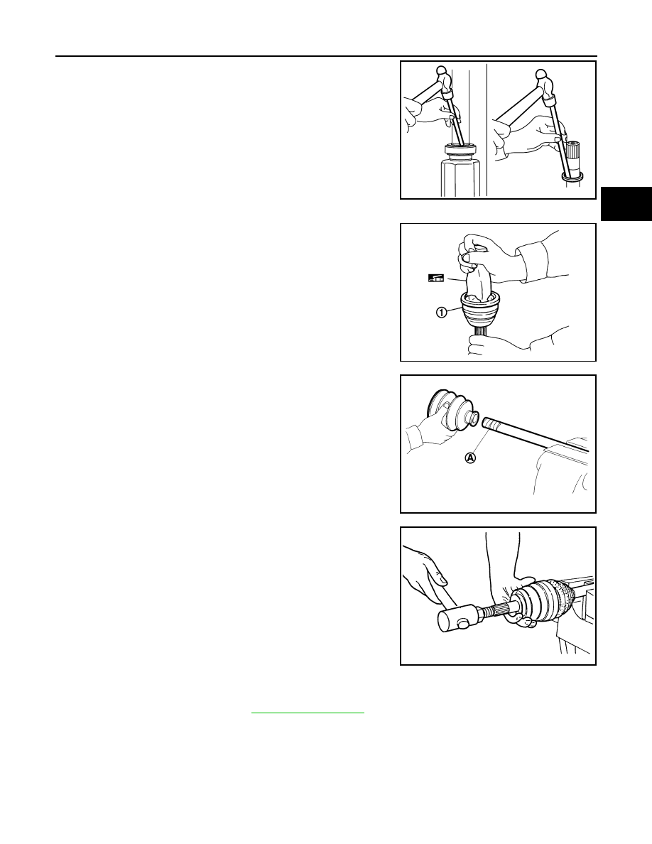
Wheel Side

1. Insert the amount of Genuine NISSAN Grease into joint sub-

assembly serration (1) hole until grease begins to ooze from ball

groove and serration hole.

CAUTION:

After inserting the grease, use a paper shop cloth to wipe

off old grease that has oozed out.

NOTE:

Always check with the Parts Department for the latest parts

information.

2. Install new boot and new small boot band onto shaft. 

CAUTION:

• Do not reuse boot and boot bands.

• Cover drive shaft serration with protective tape (A) to pre-

vent damage to boot during installation.

3. Remove protective tape wound around serrated part of shaft.

4. Attach new circlip to shaft. The circlip must fit securely into shaft

groove. Attach nut to joint sub-assembly.

Use a suitable tool to press-fit.

CAUTION:

Do not reuse circlip.

5. Insert the amount of new Genuine NISSAN Grease listed below into housing from large end of boot.

NOTE:

Always check with the Parts Department for the latest parts information.

JPDIF0127ZZ

JPDIF0008ZZ

JPDIF0009ZZ

RAC0049D

Grease quantity

: Refer to 

FAX-39, "Drive Shaft"

.

FAX-38

< UNIT DISASSEMBLY AND ASSEMBLY >

[FWD]

FRONT DRIVE SHAFT

6. Install boot securely into grooves (indicated by * marks) as

shown.

CAUTION:

If there is grease on boot mounting surfaces (indicated by *

marks) of shaft and housing, boot may come off. Remove

all grease from surfaces.

7. Make sure boot installation length (L) is the specified length.

Insert a suitable tool into the large end of boot. Bleed air from

boot to prevent boot deformation. 

CAUTION:

• Boot may break if boot installation length is less than standard value.

• Be careful that suitable tool does not contact inside surface of boot.

8. Install new large and small boot bands securely using Tool. 

CAUTION:

Do not reuse boot bands.

9. Secure boot band so that dimension (M) meets specification as

shown. 

10. After installing housing and shaft, rotate boot to check whether or not the actual position is correct. If boot

position is not correct, remove old boot bands then reposition the boot and secure with new boot bands.

Boot installation length (L) : Refer to 

FAX-39, "Drive 

Shaft"

.

Tool number

: KV40107300 (

)

JPDIF0222ZZ

RAC1133D

Dimension (M)

: Refer to 

FAX-39, "Drive 

Shaft"

.

DSF0047D

SERVICE DATA AND SPECIFICATIONS (SDS)

FAX-39

< SERVICE DATA AND SPECIFICATIONS (SDS) 

[FWD]

C

E

F

G

H

I

J

K

L

M

A

B

FAX

N

O

P

SERVICE DATA AND SPECIFICATIONS (SDS)

SERVICE DATA AND SPECIFICATIONS (SDS)

Wheel Bearing

INFOID:0000000011278638

Drive Shaft

INFOID:0000000011278639

Drive Shaft Specifications

*Always check with the Parts Department for the latest parts information.

Dynamic Damper Specifications

Unit: mm (in)

Boot Band Specification

Item

Standard

Axial end play

0.0 mm (0.0 in)

Application

FWD

Joint type

Wheel side

Transaxle side

(LH)

(RH)

(LH)

(RH)

Grease quantity*

125 

± 10 g

(4.41 

±  0.35 oz)

185 

± 10 g

(6.52 

± 0.35 oz)

Boot installed length (L)

141.5 mm (5.57 in)

176.9 mm (6.96 in)

ALDIA0269ZZ

ALDIA0268ZZ

Application

FWD

(LH)

(RH)

Dimension (A)

243 

± 3 (9.57 ± 0.12)

243 

± 3 (9.57 ± 0.12)

Dimension (B)

70 (2.76)

50 (1.97)

ALDIA0270ZZ

FAX-40

< SERVICE DATA AND SPECIFICATIONS (SDS) 

[FWD]

SERVICE DATA AND SPECIFICATIONS (SDS)

Unit: mm (in)

Dimension (M) 

1.0 - 4.0 mm (0.039 - 0.157 in)

DSF0047D


Content   ..  684  685  686  687   ..