Nissan Rogue. Manual - part 630


  Index      Nissan     Nissan Rogue (2015 year) - Service and Repair Manual


Search            


Content   ..  628  629  630  631   ..


Nissan Rogue. Manual - part 630


SYSTEM

EXL-149

< SYSTEM DESCRIPTION >

[LED HEADLAMP]

C

D

E

F

G

H

I

J

K

M

A

B

EXL

N

O

P

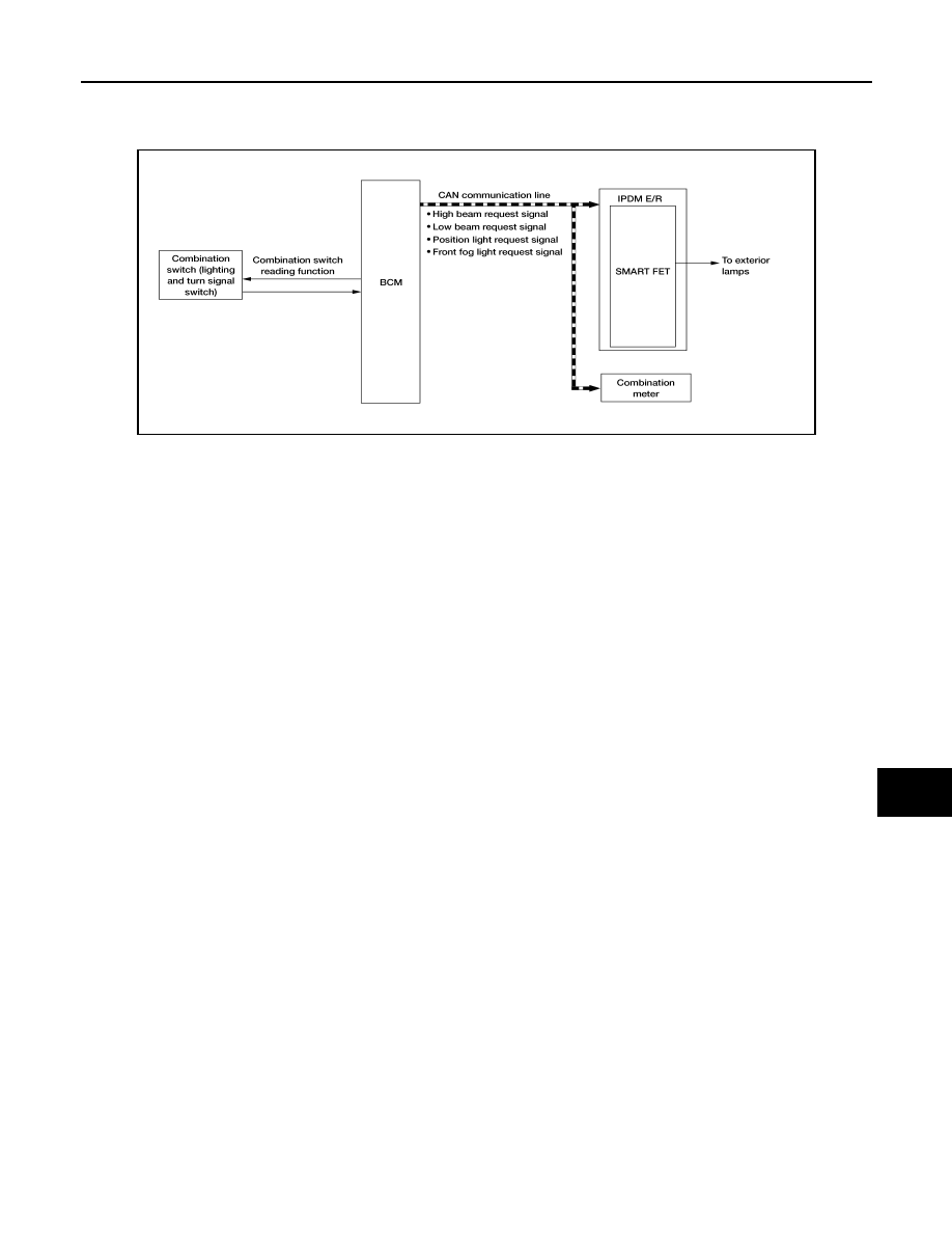
EXTERIOR LAMP BATTERY SAVER SYSTEM : System Description

INFOID:0000000011413328

SYSTEM DIAGRAM

OUTLINE

• Exterior lamp battery saver system is controlled by each function of BCM and IPDM E/R.

Controlled by BCM:

- Combination switch reading function

- Headlamp control function

- Exterior lamp battery saver function

Controlled by IPDM E/R:

- BCM turns the exterior lamps* OFF after a period of time to prevent the battery from over-discharge when

the ignition switch is turned OFF with the exterior lamps ON.

*: Headlamp (LO/HI), parking lamp, tail lamp, side marker lamp, license plate lamp and front fog lamp

EXTERIOR LAMP BATTERY SAVER ACTIVATION

BCM activates the timer and turns the exterior lamp OFF 5 minutes after the ignition switch is turned from ON

→ OFF with the exterior lamps ON. 

NOTE:

• Headlamp control function turns the exterior lamps ON normally when the ignition switch is turned ACC or 

set the vehicle to READY (both before and after the exterior lamp battery saver is turned OFF).

• The timer starts at the time that the lighting switch is turned from OFF 

→ 1ST or 2ND with the exterior lamps

OFF.

ALLIA1612GB

EXL-150

< SYSTEM DESCRIPTION >

[LED HEADLAMP]

DIAGNOSIS SYSTEM (BCM)

DIAGNOSIS SYSTEM (BCM)

WITH INTELLIGENT KEY
WITH INTELLIGENT KEY : CONSULT Function (BCM - COMMON ITEM)

INFOID:0000000011421486

APPLICATION ITEM

CONSULT performs the following functions via CAN communication with BCM.

SYSTEM APPLICATION

BCM can perform the following functions.

WITH INTELLIGENT KEY : CONSULT Function (BCM - HEADLAMP)

INFOID:0000000011421487

DATA MONITOR

Direct Diagnostic Mode

Description

Ecu Identification

The BCM part number is displayed.

Self Diagnostic Result

The BCM self diagnostic results are displayed.

Data Monitor

The BCM input/output data is displayed in real time.

Active Test

The BCM activates outputs to test components.

Work support

The settings for BCM functions can be changed.

Configuration

• The vehicle specification can be read and saved.
• The vehicle specification can be written when replacing BCM.

CAN Diag Support Mntr

The result of transmit/receive diagnosis of CAN communication is displayed.

System

Sub System

Direct Diagnostic Mode

E

cu

 Id

en

tifi

ca

tio

n

Se

lf Di

ag

no

st

ic Re

su

lt

Da

ta

 Mo

ni

tor

A

cti

ve

 T

est

W

o

rk support

Co

nf

igu

rat

ion

CA

N Diag

 Su

pp

ort Mn

tr

Door lock

DOOR LOCK

×

×

×

×

Rear window defogger

REAR DEFOGGER

×

×

×

Warning chime

BUZZER

×

×

Interior room lamp timer

INT LAMP

×

×

×

Exterior lamp

HEADLAMP

×

×

×

Wiper and washer

WIPER

×

×

×

Turn signal and hazard warning lamps FLASHER

×

×

Intelligent Key system

INTELLIGENT KEY

×

×

×

×

Combination switch

COMB SW

×

BCM

BCM

×

×

×

×

×

Immobilizer

IMMU

×

×

×

Interior room lamp battery saver

BATTERY SAVER

×

×

Back door open

TRUNK

×

Vehicle security system

THEFT ALM

×

×

×

RAP system

RETAINED PWR

×

Signal buffer system

SIGNAL BUFFER

×

Air conditioner 

AIR CONDITIONER 

×

DIAGNOSIS SYSTEM (BCM)

EXL-151

< SYSTEM DESCRIPTION >

[LED HEADLAMP]

C

D

E

F

G

H

I

J

K

M

A

B

EXL

N

O

P

ACTIVE TEST

WORK SUPPORT

Monitor Item [Unit]

Description

PUSH SW [On/Off]

Indicates condition of push-button ignition switch.

ENGINE STATE [STOP/STALL/CRANK/
RUN]

Indicates engine status received from ECM on CAN communication line.

VEH SPEED 1 [km/h]

Indicates vehicle speed signal received from ABS on CAN communication line.

TURN SIGNAL R [On/Off]

Indicates condition of combination switch.

TURN SIGNAL L [On/Off]

TAIL LAMP SW [On/Off]

HI BEAM SW [On/Off]

HEAD LAMP SW [On/Off]

LIGHT OFF SW [On/Off]

PASSING SW [On/Off]

AUTO LIGHT SW [On/Off]

FR FOG SW [On/Off]

DOOR SW-DR [On/Off]

Indicates condition of front door switch LH.

DOOR SW-AS [On/Off]

Indicates condition of front door switch RH.

DOOR SW-RR [On/Off]

Indicates condition of rear door switch RH.

DOOR SW-RL [On/Off]

Indicates condition of rear door switch LH.

DOOR SW-BK [On/Off]

Indicates condition of back door switch.

OPTI SEN (DTCT) [V]

Indicates outside brightness voltage signal from optical sensor.

OPTI SEN (FILT) [V]

Indicates outside brightness voltage signal from optical sensor filtered by BCM.

OPTICAL SENSOR [On/Off]

Indicates condition of optical sensor. 

Test Item

Description

FR FOG LAMP

This test is able to check front fog lamp operation [On/Off].

STOP LAMP 1

This test is able to check rear combination lamp stop lamp operation [On/Off].

STOP LAMP 3

This test is able to check high-mounted stop lamp operation [On/Off].

DAYTIME RUNNING LIGHT 

This test is able to check daytime running light operation [On/Off].

ILL DIM SIGNAL 

This test is able to check illumination dimmer signal [On/Off].

Support Item

Setting

Description

TWILIGHT ON

MODE2*

Autolamp function ON.

MODE1

Autolamp function OFF.

CUSTOM A/LIGHT SETTING

MODE4

Less sensitive than normal setting (turns ON later).

MODE3

More sensitive than MODE2.

MODE2

More sensitive than normal setting (turns ON earlier).

MODE1*

Normal setting.

EXL-152

< SYSTEM DESCRIPTION >

[LED HEADLAMP]

DIAGNOSIS SYSTEM (BCM)

*: Initial setting

WITH INTELLIGENT KEY : CONSULT Function (BCM - FLASHER)

INFOID:0000000011421488

DATA MONITOR

WORK SUPPORT

*: Initial setting

WITHOUT INTELLIGENT KEY
WITHOUT INTELLIGENT KEY : CONSULT Function (BCM - COMMON ITEM)

INFOID:0000000011421489

APPLICATION ITEM

CONSULT performs the following functions via CAN communication with BCM.

ILL DELAY SET

MODE 8

Autolamp delay timer.

MODE 7

MODE 6

MODE 4

MODE 5

MODE 3

MODE 2

MODE 1*

Support Item

Setting

Description

Monitor Item [Unit]

Description

REQ SW -DR [On/Off]

Indicates condition of door request switch LH.

REQ SW -AS [On/Off]

Indicates condition of door request switch RH.

PUSH SW [On/Off]

Indicates condition of push-button ignition switch.

TURN SIGNAL R [On/Off]

Indicates condition of turn signal function of combination switch.

TURN SIGNAL L [On/Off]

HAZARD SW [On/Off]

Indicates condition of hazard switch.

RKE-LOCK [On/Off]

Indicates condition of lock signal from Intelligent Key.

RKE-UNLOCK [On/Off]

Indicates condition of unlock signal from Intelligent Key.

RKE-PANIC [On/Off]

Indicates condition of panic alarm signal from Intelligent Key.

Support Item

Setting

Description

3-TIME FLASHER SETTING 

On*

3-time flasher setting ON. 

Off

3-time flasher setting OFF. 

Direct Diagnostic Mode

Description

Ecu Identification

The BCM part number is displayed.

Self Diagnostic Result

The BCM self diagnostic results are displayed.

Data Monitor

The BCM input/output data is displayed in real time.

Active Test

The BCM activates outputs to test components.

Work support

The settings for BCM functions can be changed.

Configuration

• The vehicle specification can be read and saved.
• The vehicle specification can be written when replacing BCM.

CAN Diag Support Mntr

The result of transmit/receive diagnosis of CAN communication is displayed.


Content   ..  628  629  630  631   ..