Nissan Rogue. Manual - part 629


  Index      Nissan     Nissan Rogue (2015 year) - Service and Repair Manual


Search            


Content   ..  627  628  629  630   ..


Nissan Rogue. Manual - part 629


SYSTEM

EXL-145

< SYSTEM DESCRIPTION >

[LED HEADLAMP]

C

D

E

F

G

H

I

J

K

M

A

B

EXL

N

O

P

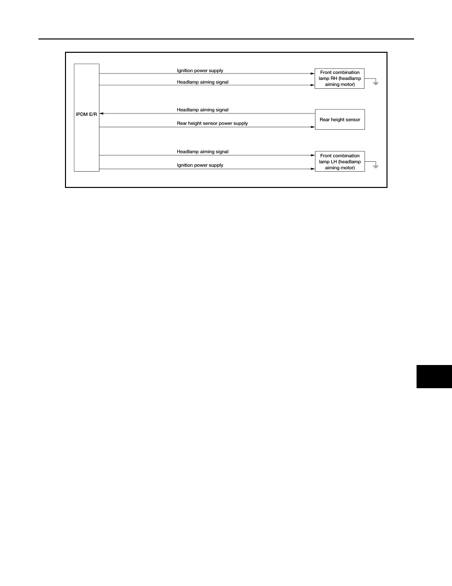
HEADLAMP AIMING CONTROL SYSTEM (AUTO) : System Diagram

INFOID:0000000011280821

HEADLAMP AIMING CONTROL SYSTEM (AUTO) : System Description

INFOID:0000000011280822

OUTLINE

• Headlamp aiming control system is controlled by the IPDM E/R.

• The IPDM E/R controls the headlamp light axis height appropriately depending on the vehicle rear height

sensor position.

• Auto levelizer control unit detects the vehicle condition necessary for the aiming motor control with the fol-

lowing signal:

- Rear height sensor signal

HEADLAMP AUTO AIMING OPERATION

• The IPDM E/R calculates vehicle pitch angle from the rear height sensor signal and determines the neces-

sary correction to compensate the deviation from standard light axis position.

• The IPDM E/R outputs aiming motor drive signal when operating conditions are met.

Operating condition:

- Ignition switch ON

- Parking lamp ON

• The IPDM E/R unit changes the aiming motor drive signal when any of the correcting conditions are

detected. Output is maintained if other condition is detected.

Correcting condition:

- Parking lamp is turned ON.

- Vehicle posture becomes stable after the vehicle posture change is detected with the parking lamp ON and

the vehicle stopped.

- Vehicle speed is maintained with the parking lamp ON and the vehicle driven.

CAUTION:

If the suspension is worn, the adjusted axis position may differ from the preset position.

TURN SIGNAL AND HAZARD WARNING LAMP SYSTEM

ALLIA1490GB

EXL-146

< SYSTEM DESCRIPTION >

[LED HEADLAMP]

SYSTEM

TURN SIGNAL AND HAZARD WARNING LAMP SYSTEM : System Description

INFOID:0000000011413323

SYSTEM DIAGRAM

OUTLINE

Turn signal lamp and the hazard warning lamp is controlled by combination switch reading function and the

flasher control function of BCM.

TURN SIGNAL LAMP OPERATION

• BCM detects the combination switch condition by the combination switch reading function.

• BCM supplies voltage to the right (left) turn signal lamp circuit when the ignition switch is ON and the turn

signal switch is in the right (left) position. BCM blinks the turn signal lamp.

HAZARD WARNING LAMP OPERATION

BCM supplies voltage to both turn signal lamp circuit when the hazard switch is ON. BCM blinks the hazard

warning lamp.

TURN SIGNAL INDICATOR LAMP AND TURN SIGNAL OPERATION

• BCM transmits the turn signal indicator lamp signal to the combination meter using CAN communication

while the turn signal lamp and the hazard warning lamp are operating.

• Combination meter outputs the turn signal sound with the integrated buzzer while blinking the turn signal

indicator lamp according to the turn signal indicator lamp signal.

HIGH FLASHER OPERATION

• BCM detects the turn signal lamp circuit status from the current value.

• BCM increases the turn signal lamp blinking speed if the bulb or harness open is detected with the turn sig-

nal lamp operating.

NOTE:

The blinking speed is normal while operating the hazard warning lamp.

PARKING, LICENSE PLATE, SIDE MARKER AND TAIL LAMP SYSTEM
PARKING, LICENSE PLATE, SIDE MARKER AND TAIL LAMP SYSTEM : System De-

ALLIA1609GB

SYSTEM

EXL-147

< SYSTEM DESCRIPTION >

[LED HEADLAMP]

C

D

E

F

G

H

I

J

K

M

A

B

EXL

N

O

P

scription

INFOID:0000000011413324

SYSTEM DIAGRAM

OUTLINE

Parking, license plate, side marker and tail lamps are controlled by combination switch reading function and

headlamp control function of BCM, and smart FET of IPDM E/R.

PARKING, LICENSE PLATE, SIDE MARKER AND TAIL LAMPS OPERATION 

• BCM detects the combination switch condition by the combination switch reading function.

• BCM transmits the position light request signal to IPDM E/R and the combination meter via CAN communi-

cation according to the ON/OFF condition of the parking, license plate, side marker and tail lamps.

Parking, license plate, side marker and tail lamps ON condition:

- Lighting switch 1ST

- Lighting switch 2ND

- Lighting switch AUTO, and the auto light function ON judgment

- Lighting switch AUTO, with the front fog lamp switch ON and the ignition switch ON

• IPDM E/R turns the parking, license plate, side marker and tail lamps ON according to the position light

request signal.

• Combination meter turns the tail lamp indicator lamp ON according to the position light request signal.

PARKING, LICENSE PLATE, SIDE MARKER AND TAIL LAMP SYSTEM : Fail-Safe

INFOID:0000000011413325

CAN COMMUNICATION CONTROL

When CAN communication with BCM is impossible, IPDM E/R performs fail-safe control. After CAN communi-

cation recovers normally, it also returns to normal control.

If no CAN communication is available with BCM

FRONT FOG LAMP SYSTEM

ALLIA1610GB

Control part

Fail-safe operation

• Parking lamp
• License plate lamp
• Illumination
• Tail  lamp
• Side marker lamp

• Turns ON the tail lamp when the ignition switch is turned ON
• Turns OFF the tail lamp when the ignition switch is turned OFF

EXL-148

< SYSTEM DESCRIPTION >

[LED HEADLAMP]

SYSTEM

FRONT FOG LAMP SYSTEM : System Description

INFOID:0000000011413326

SYSTEM DIAGRAM

OUTLINE

Front fog lamp is controlled by combination switch reading function, front fog lamp control function of BCM,

and smart FET function of IPDM E/R.

FRONT FOG LAMP OPERATION 

• BCM detects the combination switch condition by the combination switch reading function.

• BCM transmits the front fog lights request signal to IPDM E/R and the combination meter via CAN communi-

cation according to the front fog lamp ON condition.

Front fog lamp ON condition:

- Front fog lamp switch ON, and any of the following conditions are satisfied (except for the high beam ON):

• Lighting switch 2ND

• Lighting switch AUTO and the ignition switch ON

IPDM E/R turns the front fog lamp ON according to the front fog lights request signal.

Combination meter turns the front fog lamp indicator lamp ON according to the front fog lights request signal.

FRONT FOG LAMP SYSTEM : Fail-Safe

INFOID:0000000011413327

CAN COMMUNICATION CONTROL

When CAN communication with BCM is impossible, IPDM E/R performs fail-safe control. After CAN communi-

cation recovers normally, it also returns to normal control.

If no CAN communication is available with BCM

EXTERIOR LAMP BATTERY SAVER SYSTEM

ALLIA1611GB

Control part

Fail-safe operation

Front fog lamp

Front fog lamp OFF


Content   ..  627  628  629  630   ..