Nissan Rogue. Manual - part 616


  Index      Nissan     Nissan Rogue (2015 year) - Service and Repair Manual


Search            


Content   ..  614  615  616  617   ..


Nissan Rogue. Manual - part 616


TURN SIGNAL LAMP CIRCUIT

EXL-93

< DTC/CIRCUIT DIAGNOSIS >

[HALOGEN HEADLAMP]

C

D

E

F

G

H

I

J

K

M

A

B

EXL

N

O

P

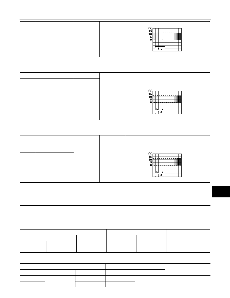
6. While the turn signal is operating, check the voltage between the door mirror harness connector and

ground.

7. While the turn signal is operating, check the voltage between the rear combination lamp harness connec-

tor and ground.

Are the inspection results normal?

YES

>> GO TO 5.

NO

>> GO TO 3.

3.

CHECK TURN SIGNAL LAMP CIRCUIT FOR OPEN 

1. Turn the ignition switch OFF.

2. Disconnect BCM harness connector E29, M18 or B23.

3. Check continuity between the BCM harness connector E29 and the front combination lamp harness con-

nector.

4. Check continuity between the BCM harness connector B23 and the door mirror harness connector. 

LH

E105

1

Ground

RH

E103

(+)

(

−)

Voltage

(Approx.)

Connector

Terminal

LH

D14

13

Ground

RH

D107 

(+)

(

−)

Voltage

(Approx.)

Connector

Terminal

LH

B90

3

Ground

RH

B102 

PKID0926E

PKID0926E

PKID0926E

BCM

Front combination lamp

Continuity

Connector

Terminal

Connector

Terminal

LH

E29

135

E105

1

Yes

RH

136

E103

BCM

Door mirror

Continuity

Connector

Terminal

Connector

Terminal

LH

M18

2

D14

13

Yes

RH

3

D107

EXL-94

< DTC/CIRCUIT DIAGNOSIS >

[HALOGEN HEADLAMP]

TURN SIGNAL LAMP CIRCUIT

5. Check continuity between the BCM harness connector B23 and the rear combination lamp harness con-

nector. 

Are the inspection results normal?

YES

>> GO TO 4.

NO

>> Repair or replace the harness or connectors.

4.

CHECK TURN SIGNAL LAMP SHORT CIRCUIT 

1. Check continuity between the BCM harness connector E29 and ground.

2. Check continuity between the BCM harness connector M18 and ground. 

3. Check continuity between the BCM harness connector M23 and ground. 

Are the inspection results normal?

YES

>> Replace BCM. Refer to 

BCS-75, "Removal and Installation"

 (with Intelligent Key system) or 

BCS-

135, "Removal and Installation"

 (without Intelligent Key system).

NO

>> Repair or replace the harness or connectors.

5.

CHECK TURN SIGNAL LAMP GROUND CIRCUIT

1. Turn the ignition switch OFF.

2. Check continuity between the front combination lamp harness connector, the door mirror connector or the

rear combination lamp harness connector in question and ground.

3. Check continuity between the door mirror harness connector and ground.

BCM

Rear combination lamp

Continuity

Connector

Terminal

Connector

Terminal

LH

B23

157

B90

3

Yes

RH

160

B102

BCM

Ground

Continuity

Connector

Terminal

LH

E29

135

No

RH

136

BCM

Ground

Continuity

Connector

Terminal

LH

B18

2

No

RH

3

BCM

Ground

Continuity

Connector

Terminal

LH

B23

157

No

RH

160

Front combination lamp

(

−)

Continuity

Connector

Terminal

LH

E105

2

Ground

Yes

RH

E103

Door mirror

(

−)

Continuity

Connector

Terminal

TURN SIGNAL LAMP CIRCUIT

EXL-95

< DTC/CIRCUIT DIAGNOSIS >

[HALOGEN HEADLAMP]

C

D

E

F

G

H

I

J

K

M

A

B

EXL

N

O

P

4. Check continuity between the rear combination lamp harness connector and ground.

Are the inspection results normal?

YES

>> Replace the malfunctioning lamp.

NO

>> Repair or replace the harness or connectors.

LH

D14

14

Ground

Yes

RH

D107

Rear combination lamp

(

−)

Continuity

Connector

Terminal

LH

B90

4

Ground

Yes

RH

B102

EXL-96

< DTC/CIRCUIT DIAGNOSIS >

[HALOGEN HEADLAMP]

B121A FRONT FOG LAMP LH POWER SUPPLY CIRCUIT

B121A FRONT FOG LAMP LH POWER SUPPLY CIRCUIT

DTC Logic

INFOID:0000000011280746

DTC DETECTION LOGIC

DTC CONFIRMATION PROCEDURE

1.

CHECK SELF DIAGNOSTIC RESULT

 With 

CONSULT.

1. Turn ignition switch ON.

2. Perform “Self Diagnostic Result”.
Is DTC B121A detected?

YES

>> Proceed to diagnosis procedure. Refer to 

EXL-96, "Diagnosis Procedure"

.

NO

>> Inspection End.

Diagnosis Procedure

INFOID:0000000011280747

1.

CHECK FOG LAMP SHORT CIRCUIT TO GROUND

1. Disconnect fog lamp connector and IPDM E/R connector.

2. Check continuity between IPDM E/R harness connector and ground.

Is the inspection result normal?

YES

>> GO TO 2.

NO

>> Repair or replace harness. 

2.

CHECK FOG LAMP SHORT CIRCUIT TO GROUND

1. Reconnect IPDM E/R connector.

2. Check continuity between fog lamp harness connector and ground.

Is the inspection result normal?

YES

>> Refer to 

GI-44, "Intermittent Incident"

.

NO

>> Replace IPDM E/R. Refer to 

PCS-40, "Removal and Installation"

DTC

Display Item

Malfunction detected condition

Possible causes

B121A

FR FOG LAMP LH PWR SPLY CIRC

 [CIRC SHORT TO GROUND

Short to ground

• IPDM E/R
• Short to ground

IPDM E/R

Ground

Continuity

Connector

Terminal

E217

51

No

Fog lamp 

Ground

Continuity

Connector

Terminal

LH

E222

1

No


Content   ..  614  615  616  617   ..