Nissan Rogue. Manual - part 592
PREPARATION
EX-3
< PREPARATION >
C
D
E
F
G
H
I
J
K
L
M
A
EX
N
P
O
PREPARATION
PREPARATION
Special Service Tool
INFOID:0000000011279724
The actual shape of the tools may differ from those illustrated here.
Commercial Service Tools
INFOID:0000000011279725
Tool number
(TechMate No.)
Tool name
Description
—
(J-43897-18)
Oxygen sensor thread cutter
Reconditioning the exhaust system threads
before installing a new oxygen sensor (Use
with anti-seize lubricant)
M18 x 1.5 threads
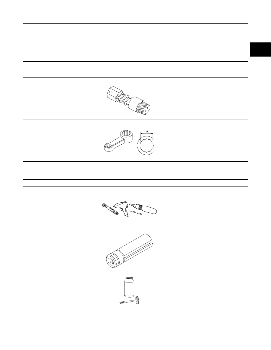
KV10114400
(J-38365)
Heated oxygen sensor wrench
Loosening or tightening heated oxygen sen-
sors:
a: 22 mm (0.87 in)
AWBIA1764ZZ
S-NT636
Tool name
Description
Power tool
Loosening nuts, screws and bolts
Heated oxygen sensor wrench
Loosening or tightening heated oxygen sen-
sor
For 22 mm (0.87 in) hexagon nut
Anti-seize lubricant (Permatex 133AR
or equivalent meeting MIL specifica-
tion MIL-A-907)
Lubricating oxygen sensor thread cleaning
tool when reconditioning exhaust system
threads
PIIB1407E
NT379
AEM489