Nissan Rogue. Manual - part 551


  Index      Nissan     Nissan Rogue (2015 year) - Service and Repair Manual


Search            


Content   ..  549  550  551  552   ..


Nissan Rogue. Manual - part 551


EC-472

< DTC/CIRCUIT DIAGNOSIS >

[QR25DE]

FUEL PUMP

YES

>> GO TO 6.

NO

>> Repair or replace error-detected parts.

6.

CHECK FUEL PUMP

Refer to 

EC-472, "Component Inspection"

.

Is the inspection result normal?

YES

>> GO TO 7.

NO

>> Replace “fuel level sensor unit and fuel pump”. Refer to 

FL-5, "Removal and Installation"

.

7.

CHECK INTERMITTENT INCIDENT

Perform 

GI-44, "Intermittent Incident"

.

Is the inspection result normal?

YES

>> Replace IPDM E/R. Refer to 

PCS-40, "Removal and Installation"

.

NO

>> Repair or replace harness or connectors.

Component Inspection

INFOID:0000000011278188

1.

CHECK FUEL PUMP

1. Turn ignition switch OFF.

2. Disconnect “fuel level sensor unit and fuel pump” harness connector.

3. Check resistance between “fuel level sensor unit and fuel pump” terminals as follows.

Is the inspection result normal?

YES

>> INSPECTION END

NO

>> Replace “fuel level sensor unit and fuel pump”. Refer to 

FL-5, "Removal and Installation"

.

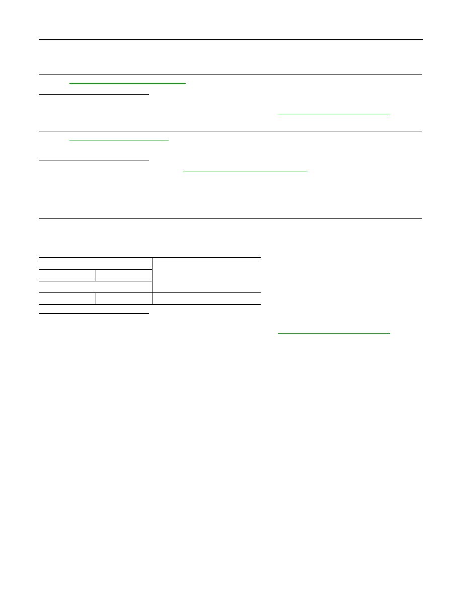
Fuel level sensor unit and fuel pump

Resistance

+

-

Terminal

6

4

0.2 - 5.0

Ω [at 25°C (77°F)]

IGNITION SIGNAL

EC-473

< DTC/CIRCUIT DIAGNOSIS >

[QR25DE]

C

D

E

F

G

H

I

J

K

L

M

A

EC

N

P

O

IGNITION SIGNAL

Component Function Check

INFOID:0000000011278189

1.

INSPECTION START

Turn ignition switch OFF, and restart engine.
Does the engine start?

YES-1 >> With CONSULT: GO TO 2.

YES-2 >> Without CONSULT: GO TO 3.

NO

>> Proceed to 

EC-473, "Diagnosis Procedure"

.

2.

CHECK IGNITION SIGNAL FUNCTION

With CONSULT

1. Perform “POWER BALANCE” in “ACTIVE TEST” mode with CONSULT.

2. Check that each circuit produces a momentary engine speed drop.
Is the inspection result normal?

YES

>> INSPECTION END

NO

>> Proceed to 

EC-473, "Diagnosis Procedure"

.

3.

CHECK IGNITION SIGNAL FUNCTION

 Without CONSULT

1. Let engine idle.

2. Read the voltage signal between ECM harness connector terminals with an oscilloscope.

NOTE:

The pulse cycle changes depending on rpm at idle.

Is the inspection result normal?

YES

>> INSPECTION END

NO

>> Proceed to 

EC-473, "Diagnosis Procedure"

.

Diagnosis Procedure

INFOID:0000000011278190

1.

CHECK ECM POWER SUPPLY

1. Turn ignition switch OFF, wait at least 10 seconds and then turn it ON.

2. Check the voltage between ECM harness connector terminals.

Is the inspection result normal?

YES

>> GO TO 2.

NO

>> Refer to 

EC-168, "Diagnosis Procedure"

.

ECM

Voltage signal

+

Connector

Terminal

Connector

Terminal

F52

86

E16

128

87

90

91

JMBIA0035GB

ECM

Voltage

Connector

+

Terminal

E16

121

128

Battery voltage

EC-474

< DTC/CIRCUIT DIAGNOSIS >

[QR25DE]

IGNITION SIGNAL

2.

CHECK CONDENSER POWER SUPPLY

1. Turn ignition switch OFF.

2. Disconnect joint connector-F01 harness connector.

3. Turn ignition switch ON.

4. Check the voltage between joint connector-F01 harness connector and ground.

Is the inspection result normal?

YES

>> GO TO 4.

NO

>> GO TO 3.

3.

CHECK CONDENSER POWER SUPPLY CIRCUIT

1. Turn ignition switch OFF.

2. Disconnect IPDM E/R harness connector.

3. Check the continuity between IPDM E/R harness connector and joint connector-F01 harness connector.

4. Also check harness for short to ground and to power.
Is the inspection result normal?

YES

>> Refer to 

EC-168, "Diagnosis Procedure"

.

NO

>> Repair open circuit, short to ground or short to power in harness or connectors.

4.

CHECK CONDENSER GROUND CIRCUIT

1. Turn ignition switch OFF.

2. Check the continuity between joint connector-F01 harness connector and ground.

3. Also check harness for short to power.
Is the inspection result normal?

YES

>> GO TO 5.

NO

>> Repair open circuit or short to power in harness or connectors.

5.

CHECK CONDENSER

Check condenser. Refer to 

EC-477, "Component Inspection (Condenser)"

Is the inspection result normal?

YES

>> GO TO 6.

NO

>> Replace condenser.

6.

CHECK IGNITION COIL POWER SUPPLY

1. Reconnect all harness connectors disconnected.

2. Disconnect ignition coil harness connector.

3. Turn ignition switch ON.

4. Check the voltage between ignition coil harness connector and ground.

+

-

Voltage

Joint connector-F01

Connector

Terminal

F8

1

Ground

Battery voltage

+

-

Continuity

IPDM E/R

Joint connector-F01

Connector

Terminal

Connector

Terminal

F35

66

F8

1

Existed

+

-

Voltage

Joint connector-F01

Connector

Terminal

F8

6

Ground

Existed

IGNITION SIGNAL

EC-475

< DTC/CIRCUIT DIAGNOSIS >

[QR25DE]

C

D

E

F

G

H

I

J

K

L

M

A

EC

N

P

O

Is the inspection result normal?

YES

>> GO TO 7.

NO

>> Repair or replace harness or connectors.

7.

CHECK IGNITION COIL GROUND CIRCUIT

1. Turn ignition switch OFF.

2. Check the continuity between ignition coil harness connector and ground.

3. Also check harness for short to power.
Is the inspection result normal?

YES

>> GO TO 8.

NO

>> Repair open circuit or short to power in harness or connectors.

8.

CHECK IGNITION COIL OUTPUT SIGNAL CIRCUIT

1. Disconnect ECM harness connector.

2. Check the continuity between ignition coil harness connector and ECM harness connector.

3. Also check harness for short to ground and to power.
Is the inspection result normal?

YES

>> GO TO 9.

NO

>> Repair open circuit, short to ground or short to power in harness or connectors.

9.

CHECK IGNITION COIL WITH POWER TRANSISTOR

Check ignition coil with power transistor. Refer to 

EC-476, "Component Inspection (Ignition Coil with Power

Transistor)"

.

Is the inspection result normal?

YES

>> Check intermittent incident. Refer to 

GI-44, "Intermittent Incident"

.

NO

>> Replace malfunctioning ignition coil with power transistor. Refer to 

EM-41, "Removal and Installa-

tion"

.

+

-

Voltage

Ignition coil

Cylinder

Connector

Terminal

1

F47

3

Ground

Battery voltage

2

F46

3

3

F48

3

4

F49

3

+

-

Continuity

Ignition coil

Cylinder

Connector

Terminal

1

F47

2

Ground

Existed

2

F46

2

3

F48

2

4

F49

2

+

-

Continuity

Ignition coil

ECM

Cylinder

Connector

Terminal

Connector

Terminal

1

F47

1

F52

86

Existed

2

F46

1

87

3

F48

1

90

4

F49

1

91


Content   ..  549  550  551  552   ..