Nissan Rogue. Manual - part 549


  Index      Nissan     Nissan Rogue (2015 year) - Service and Repair Manual


Search            


Content   ..  547  548  549  550   ..


Nissan Rogue. Manual - part 549


EC-464

< DTC/CIRCUIT DIAGNOSIS >

[QR25DE]

COOLING FAN

Is the inspection result normal?

YES

>> GO TO 12.

NO

>> Replace malfunctioning cooling fan motor. Refer to 

CO-17, "Removal and Installation"

.

12.

CHECK INTERMITTENT INCIDENT

Perform 

GI-44, "Intermittent Incident"

.

Is the inspection result normal?

YES

>> Replace IPDM E/R. Refer to 

PCS-40, "Removal and Installation"

.

NO

>> Repair or replace error-detected parts.

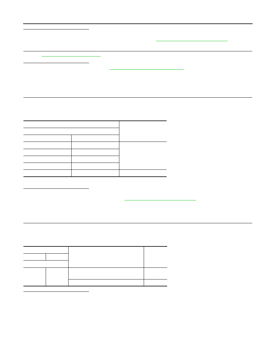
Component Inspection (Cooling Fan Motor)

INFOID:0000000011278177

1.

CHECK COOLING FAN MOTOR

1. Turn ignition switch OFF.

2. Disconnect cooling fan motor harness connector.

3. Supply cooling fan motor terminals with battery voltage and check operation.

Check that cooling fan speed of condition B is higher than that of A.

Is the inspection result normal?

YES

>> INSPECTION END

NO

>> Replace cooling fan motor. Refer to 

CO-17, "Removal and Installation"

.

Component Inspection (Cooling Fan Relay)

INFOID:0000000011278178

1.

CHECK COOLING FAN RELAYS

1. Turn ignition switch OFF.

2. Remove cooling fan relay-2, -3.

3. Check the continuity between cooling fan relay-2, -3 terminals as per the following conditions.

Is the inspection result normal?

YES

>> INSPECTION END

NO

>> Replace cooling fan relay.

Cooling fan motor

Condition

Terminal

+

1

3 and 4

A

2

3 and 4

1 and 2

3

1 and 2

4

1, 2

3, 4

B

Cooling fan relay-2, -3

Conditions

Continuity

+

Terminal

3

5

12V direct current supply between termi-
nals 1 and 2

Existed

No current supply

Not existed

ELECTRICAL LOAD SIGNAL

EC-465

< DTC/CIRCUIT DIAGNOSIS >

[QR25DE]

C

D

E

F

G

H

I

J

K

L

M

A

EC

N

P

O

ELECTRICAL LOAD SIGNAL

Description

INFOID:0000000011278179

The electrical load signal (Headlamp switch signal, rear window defogger switch signal, etc.) is transferred via

the CAN communication.

Component Function Check

INFOID:0000000011278180

1.

CHECK REAR WINDOW DEFOGGER SWITCH FUNCTION

1. Turn ignition switch ON.

2. Connect CONSULT and select “DATA MONITOR” mode.

3. Select “LOAD SIGNAL” and check indication under the following conditions.

Is the inspection result normal?

YES

>> GO TO 2.

NO

>> Proceed to 

EC-465, "Diagnosis Procedure"

.

2.

CHECK LIGHTING SWITCH FUNCTION

Check “LOAD SIGNAL” indication under the following conditions.

Is the inspection result normal?

YES

>> GO TO 3.

NO

>> Proceed to 

EC-465, "Diagnosis Procedure"

.

3.

CHECK HEATER FAN CONTROL SWITCH FUNCTION

Select “HEATER FAN SW” and check indication under the following conditions.

Is the inspection result normal?

YES

>> INSPECTION END

NO

>> Proceed to 

EC-465, "Diagnosis Procedure"

.

Diagnosis Procedure

INFOID:0000000011278181

1.

INSPECTION START

Confirm the malfunctioning circuit (rear window defogger, headlamp or heater fan). Refer to 

EC-465, "Compo-

nent Function Check"

.

Which circuit is related to the incident?

Rear window defogger>>GO TO 2.

Headlamp>>GO TO 3.

Heater fan>>GO TO 4.

2.

CHECK REAR WINDOW DEFOGGER SYSTEM

Check rear window defogger system. Refer to 

DEF-21, "Work Flow"

.

Monitor item

Condition

Indication

LOAD SIGNAL

Rear window defogger switch

ON

ON

OFF

OFF

Monitor item

Condition

Indication

LOAD SIGNAL

Lighting switch

ON at 2nd position

ON

OFF

OFF

Monitor item

Condition

Indication

HEATER FAN SW

Heater fan control switch

ON

ON

OFF

OFF

EC-466

< DTC/CIRCUIT DIAGNOSIS >

[QR25DE]

ELECTRICAL LOAD SIGNAL

>> INSPECTION END

3.

CHECK HEADLAMP SYSTEM

Check headlamp system. Refer to 

EXL-81, "Work Flow"

 (with halogen headlamp) or 

EXL-218, "Work Flow"

(with LED headlamp).

>> INSPECTION END

4.

CHECK HEATER FAN CONTROL SYSTEM

Check heater fan control system. Refer to 

HAC-46, "Work Flow"

 (with automatic air conditioner) or 

HAC-147,

"Work Flow"

 (with manual air conditioner).

>> INSPECTION END

FUEL INJECTOR

EC-467

< DTC/CIRCUIT DIAGNOSIS >

[QR25DE]

C

D

E

F

G

H

I

J

K

L

M

A

EC

N

P

O

FUEL INJECTOR

Component Function Check

INFOID:0000000011278182

1.

INSPECTION START

Turn ignition switch to START.
Are any cylinders ignited?

YES

>> GO TO 2.

NO

>> Proceed to 

EC-467, "Diagnosis Procedure"

.

2.

CHECK FUEL INJECTOR FUNCTION

 With CONSULT

1. Start engine.

2. Perform “POWER BALANCE” in “ACTIVE TEST” mode with CONSULT.

3. Check that each circuit produces a momentary engine speed drop.

Without CONSULT

1. Start engine.

2. Listen to each fuel injector operating sound.

Is the inspection result normal?

YES

>> INSPECTION END

NO

>> Proceed to 

EC-467, "Diagnosis Procedure"

.

Diagnosis Procedure

INFOID:0000000011278183

1.

CHECK FUEL INJECTOR POWER SUPPLY

1. Turn ignition switch OFF.

2. Disconnect fuel injector harness connector.

3. Turn ignition switch ON.

4. Check the voltage between fuel injector harness connector and ground.

Is the inspection result normal?

YES

>> GO TO 3.

NO

>> GO TO 2.

2.

CHECK FUEL INJECTOR POWER SUPPLY CIRCUIT

1. Turn ignition switch OFF.

2. Disconnect IPDM E/R harness connector.

3. Check the continuity between fuel injector harness connector and IPDM E/R harness connector.

Clicking sound should be heard.

PBIB3332E

+

-

Voltage

Fuel injector

Cylinder

Connector

Terminal

1

F11

1

Ground

Battery voltage

2

F12

1

3

F14

1

4

F13

1


Content   ..  547  548  549  550   ..