Nissan Rogue. Manual - part 526


  Index      Nissan     Nissan Rogue (2015 year) - Service and Repair Manual


Search            


Content   ..  524  525  526  527   ..


Nissan Rogue. Manual - part 526


EC-372

< DTC/CIRCUIT DIAGNOSIS >

[QR25DE]

P052A, P052B INTAKE VALVE TIMING CONTROL

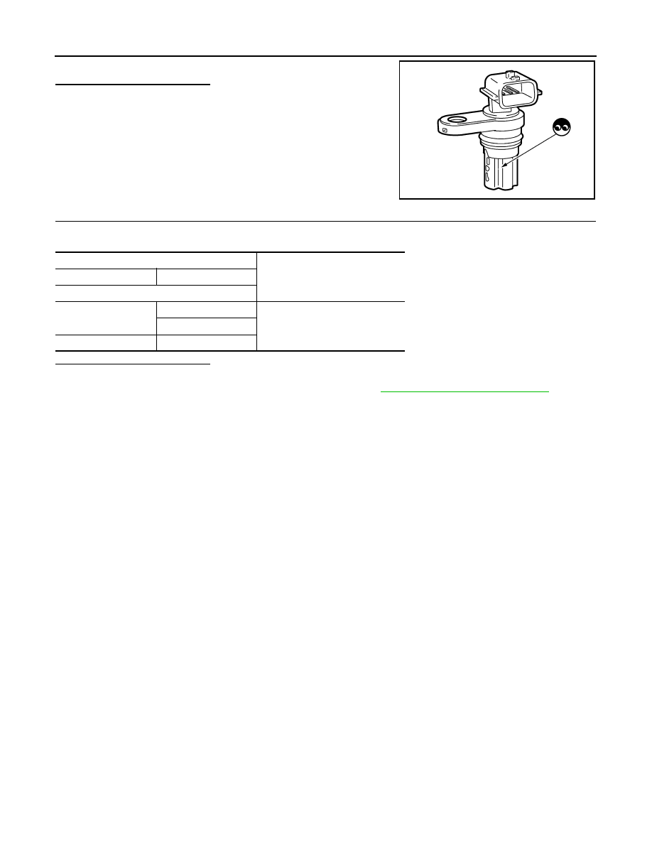
5. Visually check the sensor for chipping.
Is the inspection result normal?

YES

>> GO TO 2.

NO

>> Replace camshaft position sensor (PHASE).

2.

CHECK CAMSHAFT POSITION SENSOR (PHASE)-2

Check the resistance camshaft position sensor (PHASE) terminals as per the following.

Is the inspection result normal?

YES

>> INSPECTION END

NO

>> Replace camshaft position sensor (PHASE). Refer to 

EM-69, "Removal and Installation"

.

PBIA9876J

Camshaft position sensor (PHASE)

Resistance [

Ω at 25°C (77°F)]

+

Terminals (Polarity)

1

2

Except 0 or 

3

2

3

P0603, P062F ECM

EC-373

< DTC/CIRCUIT DIAGNOSIS >

[QR25DE]

C

D

E

F

G

H

I

J

K

L

M

A

EC

N

P

O

P0603, P062F ECM

DTC Description

INFOID:0000000011278084

DTC DETECTION LOGIC

POSSIBLE CAUSE

DTC P0603

• Harness or connectors (ECM power supply circuit is open or shorted.)

• ECM

DTC P062F

ECM

FAIL-SAFE

Not applicable

DTC CONFIRMATION PROCEDURE

1.

PRECONDITIONING

Perform the following procedure before performing DTC Confirmation Procedure.

1. Turn ignition switch OFF and wait at least 10 seconds.

2. Turn ignition switch ON.

3. Turn ignition switch OFF and wait at least 10 seconds.

>> GO TO 2.

2.

PERFORM DTC CONFIRMATION PROCEDURE FOR DTC P062F

1. Start engine and wait at least 10 seconds.

2. Turn ignition switch OFF and wait at least 10 seconds.

3. Repeat steps 1 and 2 for 4 times.

4. Turn ignition switch ON.

5. Erase DTC.

6. Turn ignition switch OFF and wait at least 10 seconds.

7. Start engine and wait at least 10 seconds.

8. Check 1st trip DTC.
Is 1st trip DTC detected?

YES

>> Proceed to 

EC-374, "Diagnosis Procedure"

.

NO

>> GO TO 3.

3.

PERFORM DTC CONFIRMATION PROCEDURE FOR DTC P0603

1. Turn ignition switch OFF and wait at least 10 seconds.

2. Turn ignition switch ON and wait at least 10 seconds.

3. Turn ignition switch OFF and wait at least 5 minutes.

4. Turn ignition switch ON and wait at least 10 seconds.

5. Repeat steps 3 and 4 for 5 times.

6. Turn ignition switch ON.

7. Check 1st trip DTC.
Is 1st trip DTC detected?

YES

>> Proceed to 

EC-374, "Diagnosis Procedure"

.

NO

>> INSPECTION END

DTC No.

CONSULT screen terms

(Trouble diagnosis content)

DTC detecting condition

P0603

ECM BACK UP/CIRCUIT
[Internal Control Module Keep Alive Memo-
ry (KAM) Error]

ECM buck up system does not function properly.

P062F

CONTROL MODULE
(Internal control module EEPROM error)

EEPROM (built-in microcomputer) system internal ECM does not function 
properly.

EC-374

< DTC/CIRCUIT DIAGNOSIS >

[QR25DE]

P0603, P062F ECM

Diagnosis Procedure

INFOID:0000000011278085

1.

INSPECTION START

Check that the battery negative terminal is not disconnected during ignition switch ON.
Is the inspection result normal?

YES

>> GO TO 3.

NO

>> GO TO 2.

2.

ERASE DTC

1. Start the engine and let it idle at least 10 seconds.

2. Turn ignition switch OFF.

3. Repeat steps 1 and 2 for 4 times.

4. Erase DTC.

5. Turn ignition switch OFF and wait at least 10 seconds.

6. Start the engine and let it idle for 10 seconds.

7. Check 1st trip DTC.
Is DTC P062F detected again?

YES

>> Replace ECM. Refer to 

EC-502, "Removal and Installation"

.

NO

>> INSPECTION END

3.

CHECK ECM POWER SUPPLY AND GROUND CIRCUIT

Check ECM power supply and ground circuit. Refer to 

EC-168, "Diagnosis Procedure"

.

Is the inspection result normal?

YES

>> GO TO 4.

NO

>> Repair or replace error-detected parts.

4.

CHECK INTERMITTENT INCIDENT

Check intermittent incident. Refer to 

GI-44, "Intermittent Incident"

.

Is the inspection result normal?

YES

>> GO TO 5.

NO

>> Repair or replace error-detected parts.

5.

PERFORM DTC CONFIRMATION PROCEDURE

1. Turn ignition switch ON.

2. Erase DTC.

3. Perform DTC confirmation procedure. Refer to 

EC-373, "DTC Description"

.

Is the DTC P0603 or P062F detected again?

YES

>> Replace ECM. Refer to 

EC-502, "Removal and Installation"

.

NO

>> INSPECTION END

P0604 ECM

EC-375

< DTC/CIRCUIT DIAGNOSIS >

[QR25DE]

C

D

E

F

G

H

I

J

K

L

M

A

EC

N

P

O

P0604 ECM

DTC Description

INFOID:0000000011278086

DTC DETECTION LOGIC

POSSIBLE CAUSE

ECM

FAIL-SAFE

Not applicable

DTC CONFIRMATION PROCEDURE

1.

PRECONDITIONING

1. Turn ignition switch OFF and wait at least 10 seconds.

2. Turn ignition switch ON.

3. Turn ignition switch OFF and wait at least 10 seconds.

TESTING CONDITION:

Before performing the following procedure, confirm that battery voltage is 11 V or more with ignition

switch ON.

>> GO TO 2.

2.

PERFORM DTC CONFIRMATION PROCEDURE

1. Turn ignition switch ON (engine stopped) and wait least 20 minutes.

CAUTION:

Never start engine during this procedure.

2. Turn ignition switch OFF and wait at least 10 seconds.

3. Turn ignition switch ON.

4. Check 1st trip DTC.
Is 1st trip DTC detected?

YES

>> Proceed to 

EC-375, "Diagnosis Procedure"

.

NO

>> INSPECTION END

Diagnosis Procedure

INFOID:0000000011278087

1.

PERFORM DTC CONFIRMATION PROCEDURE

1. Turn ignition switch ON.

2. Erase DTC.

3. Perform DTC confirmation procedure. Refer to 

EC-375, "DTC Description"

.

Is the 1st trip DTC P0604 displayed again?

YES

>> Replace ECM. Refer to 

EC-502, "Removal and Installation"

.

NO

>> INSPECTION END

DTC No.

CONSULT screen terms

(Trouble diagnosis content)

DTC detecting condition

P0604

ECM
[Internal control module random access 
memory (RAM) error]

Malfunction in the internal RAM of ECM.


Content   ..  524  525  526  527   ..