Nissan Rogue. Manual - part 455
EC-88
< ECU DIAGNOSIS INFORMATION >
[QR25DE]
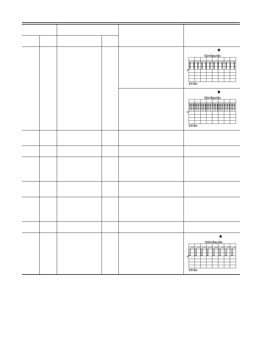
ECM
43
(LG)
42
(B)
Exhaust valve timing con-
trol position sensor
Input
[Engine is running]
• Warm-up condition
• Idle speed
NOTE:
The pulse cycle changes depending
on rpm at idle
1.0 - 2.0
[Engine is running]
• Engine speed is 2,000 rpm
1.0 - 2.0
44
(Y)
—
Sensor power supply
[Exhaust valve timing
control position sensor]
—
[Ignition switch: ON]
5 V
45
(G)
128
(BR)
A/F sensor 1
Input
[Engine is running]
• Engine speed is 2,000 rpm
1.8 V
49
(G)
128
(BR)
Intake manifold runner
control valve motor
(Close)
Output
[Ignition switch ON]
• Engine coolant temperature: Be-
tween -7
°C (19°F) and 60°C (140°F)
• Accelerator pedal: Depressed
→ ful-
ly released
Battery voltage appears for about
1 second.
50
(V)
128
(BR)
Intake manifold runner
control valve motor power
supply
Input
[Ignition switch: ON]
Battery voltage
(11 - 14 V)
51
(Y)
128
(BR)
Intake manifold runner
control valve motor
(Open)
Output
[Ignition switch ON]
• Engine coolant temperature: Be-
tween -7
°C (19°F) and 60°C (140°F)
• Accelerator pedal: Fully released
→
depressed
Battery voltage appears for about
1 second.
52
(B)
—
ECM ground
—
—
—
53
(P)
128
(BR)
A/F sensor 1 heater
Input
[Engine is running]
• Warm-up condition
• Idle speed
(More than 140 seconds after start-
ing engine)
2.9 - 8.8 V
Terminal No.
(Wire color)
Description
Condition
Value
(Approx.)
+
−
Signal name
Input/
Output
JPBIA4730ZZ
JPBIA4731ZZ
JPBIA4732ZZ