Nissan Rogue. Manual - part 454
EC-84
< ECU DIAGNOSIS INFORMATION >
[QR25DE]
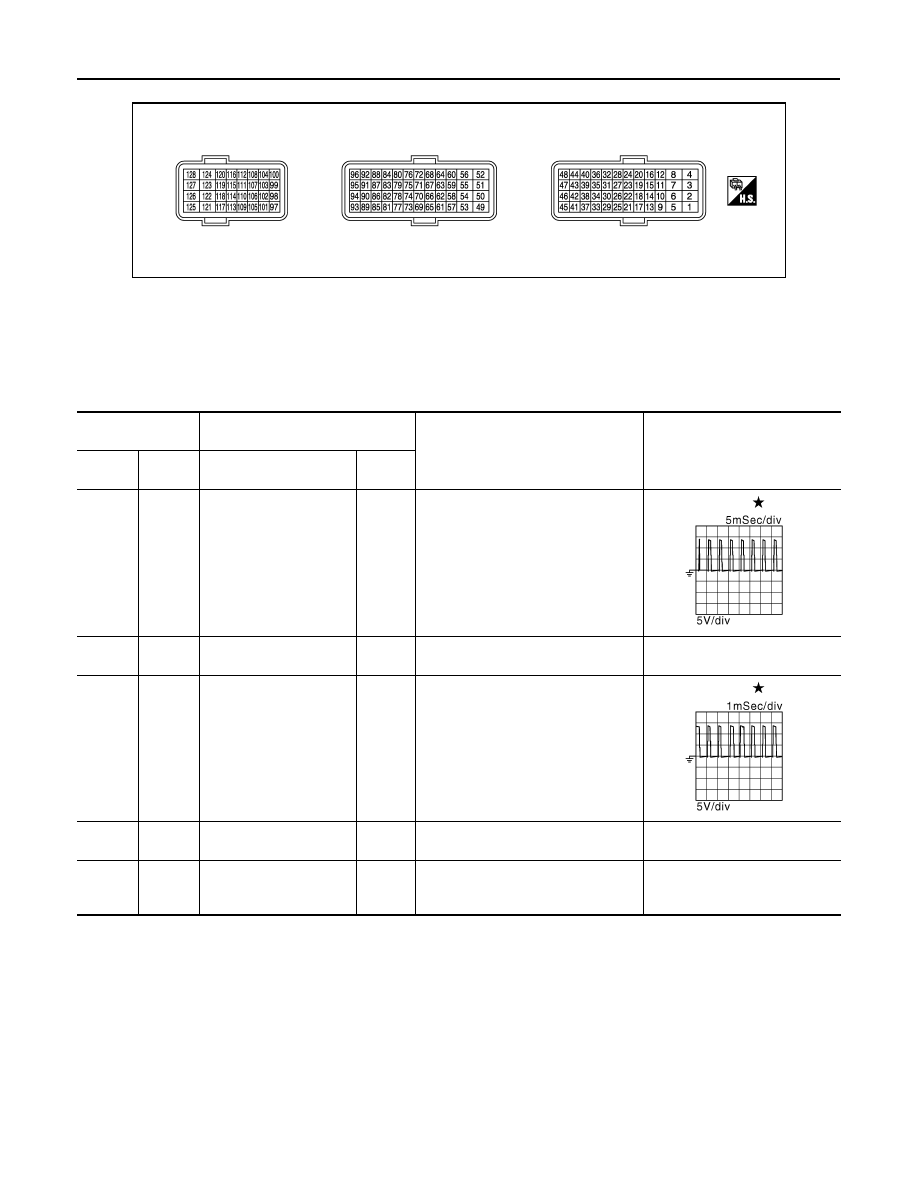
ECM
TERMINAL LAYOUT
PHYSICAL VALUES
NOTE:
• ECM is located in the engine room left side near battery.
• Specification data are reference values and are measured between each terminal and ground.
• Pulse signal is measured by CONSULT.
JSBIA0505ZZ
Terminal No.
(Wire color)
Description
Condition
Value
(Approx.)
+
−
Signal name
Input/
Output
1
(G)
128
(BR)
Throttle control motor
(Close)
Output
[Ignition switch: ON]
• Engine stopped
• Selector lever: D
• Accelerator pedal: Fully released
1.8 V
2
(GR)
128
(BR)
Throttle control motor
power supply
Input
[Ignition switch: ON]
Battery voltage
(11 - 14 V)
3
(L)
128
(BR)
Throttle control motor
(Open)
Output
[Ignition switch: ON]
• Engine stopped
• Selector lever: D
• Accelerator pedal: Fully depressed
3.2 V
4
(W)
8
(—)
Knock sensor
Input
[Engine is running]
• Idle speed
2.5 V
8
(—)
—
Sensor ground
(Knock sensor shield cir-
cuit)
—
—
—
JMBIA0326GB
JMBIA0324GB