Nissan Rogue. Manual - part 447


  Index      Nissan     Nissan Rogue (2015 year) - Service and Repair Manual


Search            


Content   ..  445  446  447  448   ..


Nissan Rogue. Manual - part 447


EC-56

< SYSTEM DESCRIPTION >

[QR25DE]

SYSTEM

Refer to 

LAN-32, "CAN COMMUNICATION SYSTEM : CAN Communication Signal Chart"

, about CAN com-

munication for detail.
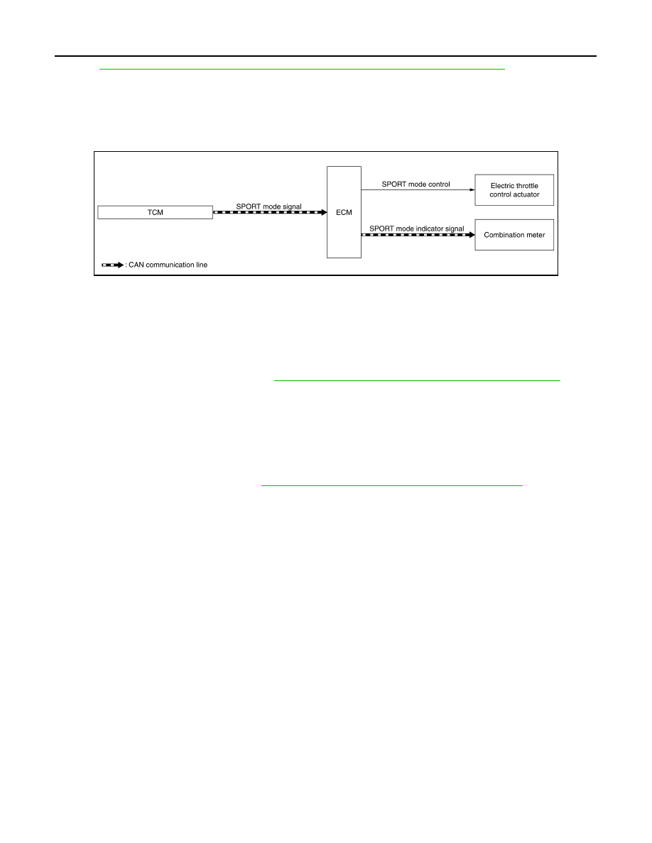
SPORT MODE CONTROL
SPORT MODE CONTROL : System Description

INFOID:0000000011277873

SYSTEM DIAGRAM

SYSTEM DESCRIPTION

• SPORT mode that keeps high engine revolution and provides direct feel and acceleration performance suit-

able for driving on winding road.

• ECM receives an SPORT mode signal from TCM via CAN communication and improves drivability by con-

trolling the throttle movement.

• ECM transmits an SPORT mode indicator lamp signal to the combination meter via CAN communication.

NOTE:

For the details of the SPORT mode, refer to 

DMS-8, "SPORT MODE CONTROL : System Description"

.

ECO MODE CONTROL
ECO MODE CONTROL : System Description

INFOID:0000000011518220

SYSTEM DESCRIPTION

ECM receives an ECO mode signal from TCM via CAN communication and improves the fuel economy by

controlling the throttle movement to less than usual.

For details of ECO mode system, refer to 

TM-43, "ECO MODE SYSTEM : System Description"

.

JSBIA3227GB

OPERATION

EC-57

< SYSTEM DESCRIPTION >

[QR25DE]

C

D

E

F

G

H

I

J

K

L

M

A

EC

N

P

O

OPERATION

AUTOMATIC SPEED CONTROL DEVICE (ASCD)
AUTOMATIC SPEED CONTROL DEVICE (ASCD) : Switch Name and Function

INFOID:0000000011277874

SWITCHES AND INDICATORS

SET SPEED RANGE

ASCD system can be set the following vehicle speed.

SWITCH OPERATION

Refer to 

EC-49, "AUTOMATIC SPEED CONTROL DEVICE (ASCD) : System Description"

 for ASCD operating

instructions.

On the combination meter

On the steering wheel

CRUISE indicator 

SET indicator CANCEL 

switch

ACCEL/RES switch

COAST/SET switch

ASCD MAIN switch

JPBIA5872ZZ

Minimum speed (Approx.)

Maximum speed (Approx.)

40 km/h (25 MPH)

144 km/h (90 MPH)

Item

Function

CANCEL switch

Cancels the cruise control driving. 

ACCEL/RES switch

• Resumes the set speed.
• Increases speed incrementally during cruise control driving.

COAST/SET switch

• Sets desired cruise speed.
• Decreases speed incrementally during cruise control driving.

ASCD MAIN switch

Master switch to activate the ASCD system.

EC-58

< SYSTEM DESCRIPTION >

[QR25DE]

ON BOARD DIAGNOSTIC (OBD) SYSTEM

ON BOARD DIAGNOSTIC (OBD) SYSTEM

Diagnosis Description

INFOID:0000000011277875

This system is an on board diagnostic system that records exhaust emission-related diagnostic information

and detects a sensors/actuator-related malfunction. A malfunction is indicated by the malfunction indicator

lamp (MIL) and stored in control module memory as a DTC. The diagnostic information can be obtained with

the diagnostic tool (GST: Generic Scan Tool).

GST (Generic Scan Tool)

INFOID:0000000011277876

When GST is connected with a data link connector equipped on the vehicle side, it will communicate with the

control module equipped in the vehicle and then enable various kinds of diagnostic tests. Refer to 

EC-58,

"Diagnosis Description"

.

NOTE:

Service $0A is not applied for regions where it is not mandated.

DIAGNOSIS SYSTEM (ECM)

EC-59

< SYSTEM DESCRIPTION >

[QR25DE]

C

D

E

F

G

H

I

J

K

L

M

A

EC

N

P

O

DIAGNOSIS SYSTEM (ECM)

DIAGNOSIS DESCRIPTION
DIAGNOSIS DESCRIPTION : 1st Trip Detection Logic and Two Trip Detection Logic

INFOID:0000000011277877

When a malfunction is detected for the first time, 1st trip DTC and 1st trip Freeze Frame data are stored in the

ECM memory. The MIL will not illuminate at this stage. <1st trip>

If the same malfunction is detected again during the next drive, the DTC and Freeze Frame data are stored in

the ECM memory, and the MIL illuminates. The MIL illuminates at the same time when the DTC is stored.

<2nd trip> The “trip” in the “Two Trip Detection Logic” means a driving mode in which self-diagnosis is per-

formed during vehicle operation. Specific on board diagnostic items will cause the ECM to illuminate or blink

the MIL, and store DTC and Freeze Frame data, even in the 1st trip, as shown below.

×: Applicable —: Not applicable

DIAGNOSIS DESCRIPTION : DTC and Freeze Frame Data

INFOID:0000000011277878

DTC AND 1ST TRIP DTC

The 1st trip DTC (whose number is the same as the DTC number) is displayed for the latest self-diagnostic

result obtained. If the ECM memory was cleared previously, and the 1st trip DTC did not recur, the 1st trip DTC

will not be displayed.

If a malfunction is detected during the 1st trip, the 1st trip DTC is saved in the ECM memory. The MIL will not

light up (two trip detection logic). If the same malfunction is not detected in the 2nd trip (meeting the required

driving pattern), the 1st trip DTC is cleared from the ECM memory. If the same malfunction is detected in the

2nd trip, both the 1st trip DTC and DTC are saved in the ECM memory and the MIL lights up. In other words,

the DTC is stored in the ECM memory and the MIL lights up when the same malfunction occurs in two consec-

utive trips. If a 1st trip DTC is stored and a non-diagnostic operation is performed between the 1st and 2nd

trips, only the 1st trip DTC will continue to be stored. For malfunctions that blink or light up the MIL during the

1st trip, the DTC and 1st trip DTC are stored in the ECM memory.

For malfunctions in which 1st trip DTCs are displayed, refer to 

EC-96, "DTC Index"

. These items are required

by legal regulations to continuously monitor the system/component. In addition, the items monitored non-con-

tinuously are also displayed on CONSULT.

1st trip DTC is specified in Service $07 of SAE J1979/ISO 15031-5. 1st trip DTC detection occurs without illu-

minating the MIL and therefore does not warn the driver of a malfunction.

When a 1st trip DTC is detected, check, print out or write down and erase (1st trip) DTC and Freeze Frame

data as specified in Work Flow procedure Step 2, refer to 

EC-130, "Work Flow"

. Then perform DTC Confirma-

tion Procedure or Component Function Check to try to duplicate the malfunction. If the malfunction is dupli-

cated, the item requires repair.

FREEZE FRAME DATA AND 1ST TRIP FREEZE FRAME DATA

The ECM records the driving conditions such as fuel system status, calculated load value, engine coolant tem-

perature, short term fuel trim, long term fuel trim, engine speed, vehicle speed, absolute throttle position, base

fuel schedule and intake air temperature at the moment a malfunction is detected.

Data which are stored in the ECM memory, along with the 1st trip DTC, are called 1st trip freeze frame data.

The data, stored together with the DTC data, are called freeze frame data and displayed on CONSULT or

GST. The 1st trip freeze frame data can only be displayed on the CONSULT screen.

Items

MIL

DTC

1st trip DTC

1st trip

2nd trip 

1st trip 

displaying

2nd trip 

displaying

1st trip 

displaying

2nd trip 

display-

ing

Blinking

Illuminat-

ed

Blinking

Illuminat-

ed

Misfire (Possible three way catalyst 
damage) — DTC: P0300 – P0304 
is being detected

×

×

Misfire (Possible three way catalyst 
damage) — DTC: P0300 – P0304 
is being detected

×

×

One trip detection diagnoses (Re-
fer to 

EC-96, "DTC Index"

.)

×

×

Except above

×

×

×


Content   ..  445  446  447  448   ..