Nissan Rogue. Manual - part 424


  Index      Nissan     Nissan Rogue (2015 year) - Service and Repair Manual


Search            


Content   ..  422  423  424  425   ..


Nissan Rogue. Manual - part 424


DLN-140

< UNIT DISASSEMBLY AND ASSEMBLY >

[REAR FINAL DRIVE: R145]

DRIVE PINION

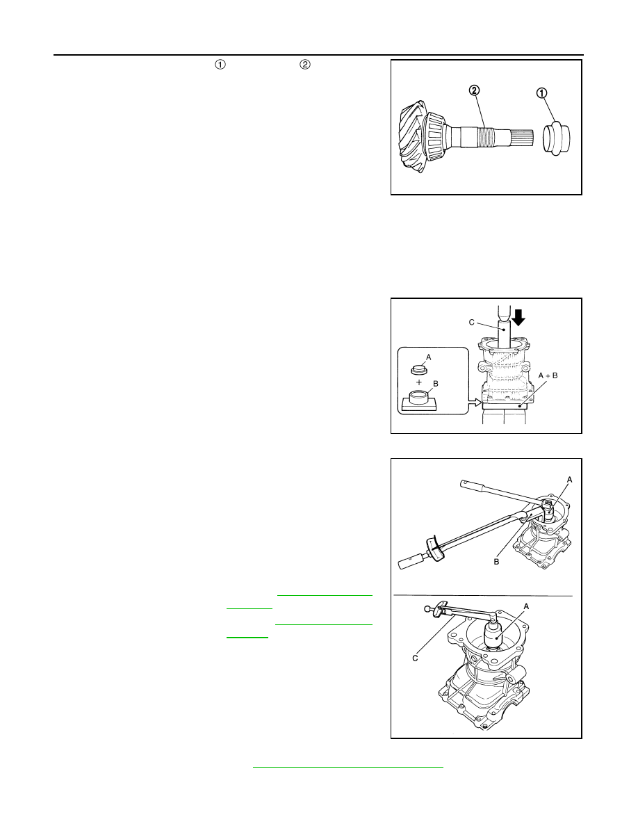
5. Assemble collapsible spacer   to drive pinion  .

CAUTION:

• Be careful of the mounting direction of collapsible spacer.

• Never reuse collapsible spacer.

6. Assemble drive pinion into gear carrier.

CAUTION:

Apply gear oil to pinion rear bearing.

7. Assemble pinion front bearing inner race to drive pinion assembly.

CAUTION:

• Never reuse pinion front bearing inner race.

• Apply gear oil to pinion front bearing.

8. Using the drifts (A and C) and press stand (B), press pinion front

bearing inner race to drive pinion as far as drive pinion lock nut

can be tightened.

9. Apply anti-corrosion oil to the thread and seat of drive pinion

lock nut, and temporarily tighten drive pinion lock nut to drive

pinion.

CAUTION:

Never reuse drive pinion lock nut.

10. Fit the drive pinion socket (A) onto the drive pinion. While hold-

ing drive pinion, tighten drive pinion lock nut within the limits of

specified torque so as to keep the pinion bearing preload within

a standard values, using the pinion nut wrench (B) and the pre-

load gauge (C).

CAUTION:

• Adjust the lower limit of the drive pinion lock nut tighten-

ing torque first.

• If the preload torque exceeds the specified value, replace

collapsible spacer and tighten it again to adjust. Never

loose n drive pinion lock nut to adjust the preload torque.

• After adjustment, rotate drive pinion back and forth 2 to 3

times to check for unusual noise, rotation malfunction,

and other malfunctions.

11. Install differential assembly. Refer to 

DLN-126, "Disassembly and Assembly"

.

CAUTION:

Never install rear cover at this timing.

JSDIA0317ZZ

A

: Drift [SST: KV40100610 (J-26089)]

B

: Press stand [SST: ST38220000 ( — )]

C

: Drift [SST: ST23860000 ( — )]

A

: Drive pinion socket [SST: KV38109500 ( — )]

B

: Pinion nut wrench [SST: KV38109400 ( — )]

C

: Preload gauge [SST: ST3127S000 (J-25765-A)]

Drive pinion lock nut 
tightening torque

: Refer to 

DLN-136, "Explod-

ed View"

.

Pinion bearing preload

: Refer to 

DLN-142, "Preload 

Torque"

.

JSDIA5302ZZ

JSDIA0266ZZ

DRIVE PINION

DLN-141

< UNIT DISASSEMBLY AND ASSEMBLY >

[REAR FINAL DRIVE: R145]

C

E

F

G

H

I

J

K

L

M

A

B

DLN

N

O

P

12. Check and adjust drive gear runout, tooth contact, and drive gear to drive pinion backlash. Refer to 

DLN-

131, "Adjustment"

.

13. Remove dummy cover set [SST: KV381086S1 ( — )], then install rear cover, and side oil seal. Refer to

DLN-126, "Disassembly and Assembly"

.

14. Check total preload torque. Refer to 

DLN-131, "Adjustment"

.

15. Using the drift (A) [SST: ST35271000 (J-26091)], install drive

pinion oil seal   within the dimension (D) shown as follows.

CAUTION:

• Never reuse oil seal.

• When installing, never incline oil seal.

• Apply multi-purpose grease onto oil seal lips, and gear oil

onto the circumference of oil seal.

16. Install electric controlled coupling assembly. Refer to 

DLN-122,

"Disassembly and Assembly"

.

Inspection

INFOID:0000000011278426

INSPECTION AFTER DISASSEMBLY

Drive Gear and Drive Pinion

• Clean up the disassembled parts.

• If the gear teeth never mesh or line-up correctly, determine the cause and adjust or replace as necessary.

• If the gears are worn, cracked, damaged, pitted or chipped (by friction) noticeably, replace with new drive

gear and drive pinion as a set.

Bearing

• Clean up the disassembled parts.

• If any chipped (by friction), pitted, worn, rusted or scratched marks, or unusual noise from the bearing is

observed, replace as a bearing assembly (as a new set).

Oil Seal

• Whenever disassembled, replace.

• If wear, deterioration of adherence (sealing force lips), or damage is detected on the lips, replace them.

D

: 0.8 – 1.2 mm (0.031 – 0.047 in)

JSDIA5262ZZ

DLN-142

< SERVICE DATA AND SPECIFICATIONS (SDS) 

[REAR FINAL DRIVE: R145]

SERVICE DATA AND SPECIFICATIONS (SDS)

SERVICE DATA AND SPECIFICATIONS (SDS)

SERVICE DATA AND SPECIFICATIONS (SDS)

General Specifications

INFOID:0000000011278427

Preload Torque

INFOID:0000000011278428

Unit: N·m (kg-m, in-lb)

Drive Gear Runout

INFOID:0000000011278429

Unit: mm (in)

Backlash

INFOID:0000000011278430

Unit: mm (in)

Differential Side Gear Clearance

INFOID:0000000011278431

Unit: mm (in)

Applied model

AWD

QR25DE

CVT

Final drive model

R145

Gear ratio

2.466

Number of teeth (Drive gear/Drive pinion)

37/15

Number of pinion gears

2

Drive pinion adjustment spacer type

Collapsible

Oil

Recommended oil

Refer to 

MA-11, "Fluids and Lubricants"

.

Oil capacity (Approx.)

 (US pt, Imp pt)

0.55 (1-1/8, 1)

Item

Standard

Pinion bearing (P

1

)

0.69 – 1.18 (0.07 – 0.12, 7 – 10)

Side bearing (P

2

)

0.66 – 1.00 (0.07 – 0.10, 6 – 8)

Side bearing to pinion bearing (Total preload)
(Total preload = P

1

 + P

2

)

1.35 – 2.18 (0.14 – 0.22, 12 – 19)

Item

Standard

Drive gear back face runout

0.05 (0.0020) or less

Item

Standard

Drive gear to drive pinion gear

0.10 – 0.15 (0.0039 – 0.0059)

Item

Standard

Side gear backlash (Clearance between side gear and differential 
case)

0.10 (0.004) or less

(Each gear should rotate smoothly without excessive resistance 

during differential motion.)

DMS-1

CRUISE CONTROL

C

D

E

F

G

H

I

J

K

L

M

B

DMS

SECTION 

DMS

N

P

A

CONTENTS

DRIVE MODE SYSTEM

SPORT MODE

PRECAUTION ...............................................

3

PRECAUTIONS ...................................................

3

Precaution for Supplemental Restraint System 
(SRS) "AIR BAG" and "SEAT BELT PRE-TEN-
SIONER" .................................................................
..

3

Precaution for Work  ..................................................

3

PREPARATION ............................................

4

PREPARATION ...................................................

4

Special Service Tool  .................................................

4

SYSTEM DESCRIPTION  ..............................

5

COMPONENT PARTS  ........................................

5

Component Parts Location ........................................

5

SPORT Mode Switch  ................................................

6

SPORT Mode Indicator Lamp  ...................................

6

SYSTEM ..............................................................

8

SPORT MODE CONTROL  ..........................................

8

SPORT MODE CONTROL : System Description ......

8

ECU DIAGNOSIS INFORMATION  ...............

9

SPORT MODE .....................................................

9

List of ECU Reference  ..............................................

9

WIRING DIAGRAM ......................................

10

SPORT MODE SYSTEM  ....................................

10

Wiring Diagram  .......................................................

10

BASIC INSPECTION  ...................................

14

DIAGNOSIS AND REPAIR WORK FLOW  ........

14

Work Flow  ...............................................................

14

DTC/CIRCUIT DIAGNOSIS  .........................

15

SPORT MODE SWITCH  ...................................

15

Component Function Check  ....................................

15

Diagnosis Procedure  ...............................................

15

Component Inspection .............................................

16

SYMPTOM DIAGNOSIS  ..............................

17

THE SPORT MODE INDICATOR LAMP 
DOES NOT TURN ON .......................................

17

Description ...............................................................

17

Diagnosis Procedure  ...............................................

17

REMOVAL AND INSTALLATION ...............

18

SPORT MODE SWITCH  ...................................

18

Removal and Installation  .........................................

18

ECO MODE

PRECAUTION ..............................................

19

PRECAUTIONS .................................................

19

Precaution for Supplemental Restraint System 
(SRS) "AIR BAG" and "SEAT BELT PRE-TEN-
SIONER" .................................................................

19

Precaution for Work .................................................

19

PREPARATION ...........................................

20

PREPARATION .................................................

20

Special Service Tool ................................................

20

SYSTEM DESCRIPTION  .............................

21

COMPONENT PARTS  ......................................

21

Component Parts Location  ......................................

21

ECO Mode Switch  ...................................................

22

ECO Mode Indicator Lamp  ......................................

22

SYSTEM ............................................................

23

ECO MODE CONTROL  .............................................

23

ECO MODE CONTROL : System Description  ........

23


Content   ..  422  423  424  425   ..