Nissan Rogue. Manual - part 415


  Index      Nissan     Nissan Rogue (2015 year) - Service and Repair Manual


Search            


Content   ..  413  414  415  416   ..


Nissan Rogue. Manual - part 415


DLN-104

< SERVICE DATA AND SPECIFICATIONS (SDS) 

[REAR PROPELLER SHAFT: C-CVJ-C]

SERVICE DATA AND SPECIFICATIONS (SDS)

SERVICE DATA AND SPECIFICATIONS (SDS)

SERVICE DATA AND SPECIFICATIONS (SDS)

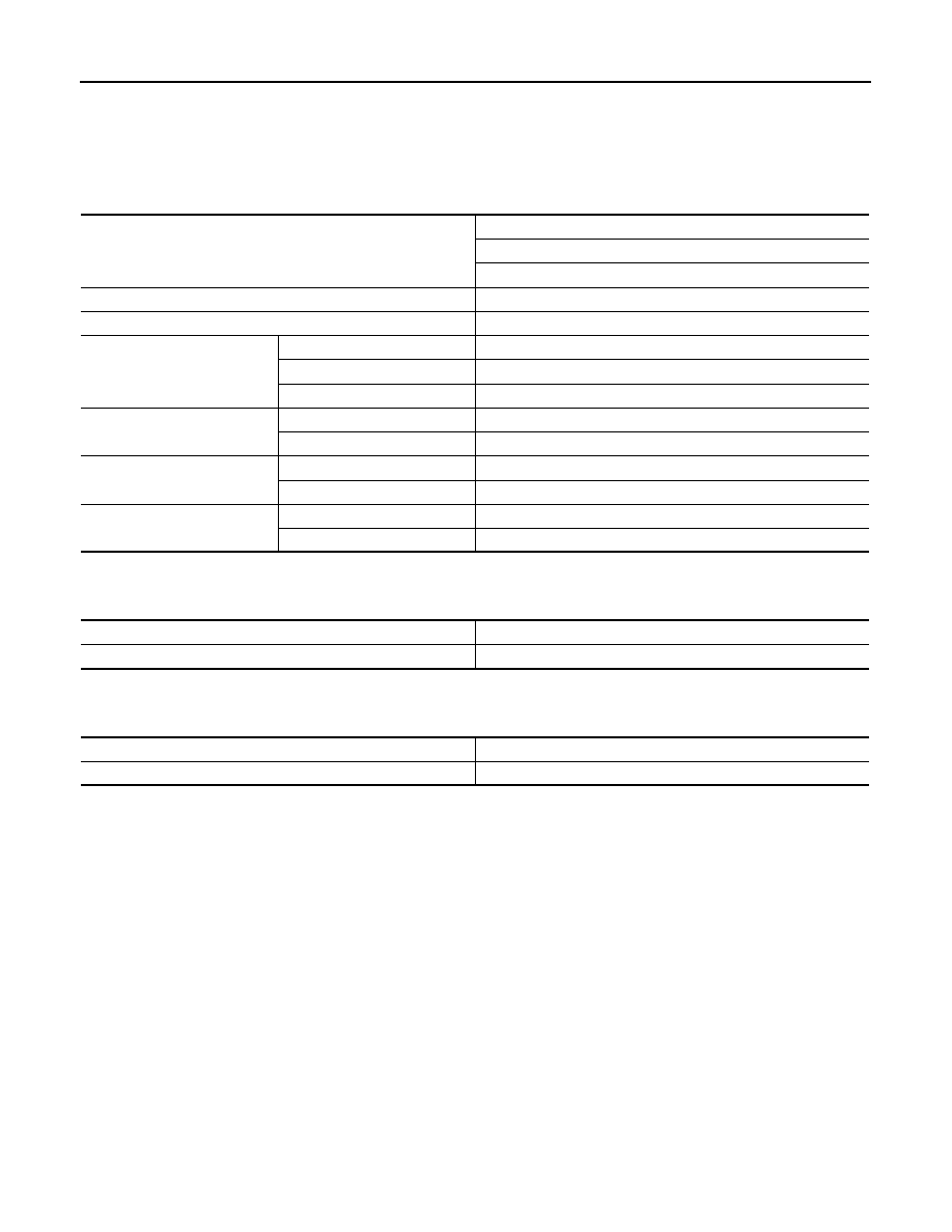
General Specifications

INFOID:0000000011278395

Propeller Shaft Runout

INFOID:0000000011278396

Unit: mm (in)

Journal Axial Play

INFOID:0000000011278397

Unit: mm (in)

Applied model

AWD

QR25DE

CVT

Propeller shaft model

C-CVJ-C

Number of joints

3

Joint type

1st joint

Universal (Shell type)

2nd joint

CVJ type

3rd joint

Universal (Shell type)

Coupling method

Transfer side

Flange type

Rear final drive side

Flange type

Shaft length

1st (Spider to CVJ joint center)

1196 mm (47.09 in)

2nd (CVJ joint center to spider)

983 mm (38.70 in)

Shaft outer diameter

1st

63.5 mm (2.500 in)

2nd

70.0 mm (2.756 in)

Item

Standard

Propeller shaft runout

0.6 (0.024) or less

Item

Standard

Journal axial play

0 (0)

PRECAUTIONS

DLN-105

< PRECAUTION >

[REAR FINAL DRIVE: R145]

C

E

F

G

H

I

J

K

L

M

A

B

DLN

N

O

P

PRECAUTION

PRECAUTIONS

Precaution for Supplemental Restraint System (SRS) "AIR BAG" and "SEAT BELT 
PRE-TENSIONER"

INFOID:0000000011278398

The Supplemental Restraint System such as “AIR BAG” and “SEAT BELT PRE-TENSIONER”, used along

with a front seat belt, helps to reduce the risk or severity of injury to the driver and front passenger for certain

types of collision. Information necessary to service the system safely is included in the SR and SB section of

this Service Manual.

WARNING:

• To avoid rendering the SRS inoperative, which could increase the risk of personal injury or death in

the event of a collision which would result in air bag inflation, all maintenance must be performed by

an authorized NISSAN/INFINITI dealer.

• Improper maintenance, including incorrect removal and installation of the SRS, can lead to personal

injury caused by unintentional activation of the system. For removal of Spiral Cable and Air Bag

Module, see the SR section.

• Do not use electrical test equipment on any circuit related to the SRS unless instructed to in this

Service Manual. SRS wiring harnesses can be identified by yellow and/or orange harnesses or har-

ness connectors.

PRECAUTIONS WHEN USING POWER TOOLS (AIR OR ELECTRIC) AND HAMMERS

WARNING:

• When working near the Airbag Diagnosis Sensor Unit or other Airbag System sensors with the Igni-

tion ON or engine running, DO NOT use air or electric power tools or strike near the sensor(s) with a

hammer. Heavy vibration could activate the sensor(s) and deploy the air bag(s), possibly causing

serious injury.

• When using air or electric power tools or hammers, always switch the Ignition OFF, disconnect the

battery and wait at least three minutes before performing any service.

Service Notice or Precautions for Rear Final Drive

INFOID:0000000011278399

• Check for the correct installation status prior to removal or disassembly. If matching marks are required, be

certain they never interfere with the function of the parts when applied.

• Overhaul should be done in a clean work area, it is preferable to work in dustproof area.

• Before disassembly, using steam or white gasoline, completely remove sand and mud from the exterior of

the unit, preventing them from entering into the unit during disassembly or assembly.

• Check appearance of the disassembled parts for damage, deformation, and unusual wear. Replace them

with a new ones if necessary.

• Gaskets, seals and O-rings should be replaced any time when the unit is disassembled.

• In principle, tighten bolts or nuts gradually in several steps working diagonally from inside to outside. If tight-

ening sequence is specified, observe it.

• Clean and flush the parts sufficiently and blow-dry them.

• Be careful not to damage sliding surfaces and mating surfaces.

• When applying sealant, remove the old sealant from the mounting surface; then remove any moisture, oil,

and foreign materials from the application and mounting surfaces.

• Always use shop paper for cleaning the inside of components.

• Never use cotton gloves or shop rags to prevent entering of lint.

• During assembly, observe the specified tightening torque, and apply new gear oil, petroleum jelly, or multi-

purpose grease as specified for each vehicle, if necessary.

DLN-106

< PREPARATION >

[REAR FINAL DRIVE: R145]

PREPARATION

PREPARATION

PREPARATION

Special Service Tools

INFOID:0000000011278400

The actual shape of the tools may differ from those illustrated here.

Tool number
(TechMate No.)
Tool name

Description

KV38100200
(J-26233)
Drift
a: 65 mm (2.56 in) dia.
b: 49 mm (1.93 in) dia.

• Installing drive pinion oil seal
• Installing side oil seal

ST27861000
(

)

Drift
a: 62 mm (2.44 in) dia.
b: 52 mm (2.05 in) dia.

Installing drive pinion oil seal

ST35271000
(J-26091)
Drift
a: 72 mm (2.83 in) dia.
b: 63 mm (2.48 in) dia.

Installing drive pinion oil seal

KV40100610
(J-26089)
Drift
a: 63 mm (2.48 in) dia.
b: 54.3 mm (2.138 in) dia.

• Removing and installing gear carrier and 

rear cover (2 pieces are used)

• Installing pinion front bearing inner race

ST33052000
(

)

Adaptor
a: 22 mm (0.87 in) dia.
b: 28 mm (1.10 in) dia.

Removing side bearing inner race

KV40105020
(

)

Drift
a: 39.7 mm (1.563 in) dia.
b: 35 mm (1.38 in) dia.
c: 15 mm (0.59 in)

Installing side bearing inner race

ZZA1143D

ZZA0832D

ZZA0814D

ZZA1000D

ZZA1023D

ZZA1133D

PREPARATION

DLN-107

< PREPARATION >

[REAR FINAL DRIVE: R145]

C

E

F

G

H

I

J

K

L

M

A

B

DLN

N

O

P

KV38109500
(

)

Drive pinion socket

• Removing and installing drive pinion lock 

nut

• Measuring preload torque

KV38109400
(

)

Pinion nut wrench

Removing and installing drive pinion lock nut

ST33200000
(J-26082)
Drift
a: 60 mm (2.36 in) dia.
b: 44.5 mm (1.752 in) dia.

Installing pinion rear bearing outer race

ST33230000
(J-25805-01)
Drift
a: 51 mm (2.01 in) dia.
b: 41 mm (1.61 in) dia.
c: 28.5 mm (1.122 in) dia.

Installing pinion front bearing outer race

ST23860000
(

)

Drift
a: 38 mm (1.50 in) dia.
b: 33 mm (1.30 in) dia.

• Installing pinion rear bearing inner race
• Installing pinion front bearing inner race

ST38220000
(

)

Press stand
a: 63 mm (2.48 in) dia.
b: 65 mm (2.56 in)

Installing pinion front bearing inner race

Tool number
(TechMate No.)
Tool name

Description

ZZA1205D

ZZA1206D

ZZA1002D

ZZA1046D

ZZA0534D

ZZA1058D


Content   ..  413  414  415  416   ..