Nissan Rogue. Manual - part 273
DAS
U1A35-00 BRAKE CONTROL COMMUNICATION
DAS-263
< DTC/CIRCUIT DIAGNOSIS >
[CHASSIS CONTROL]
C
D
E
F
G
H
I
J
K
L
M
B
N
P
A
U1A35-00 BRAKE CONTROL COMMUNICATION
DTC Description
INFOID:0000000011277434
DTC DETECTION LOGIC
POSSIBLE CAUSE
• ABS actuator and electric unit (control unit)
• Chassis control module
• CAN communication line
FAIL-SAFE
The following functions are suspended:
• Active Trace Control function
• Active Ride Control function
• Active Engine Brake function
DTC CONFIRMATION PROCEDURE
1.
PRECONDITIONING
If “DTC CONFIRMATION PROCEDURE” has been previously conducted, always turn the ignition switch OFF
and wait at least 10 seconds before conducting the next test.
>> GO TO 2.
2.
CHECK DTC DETECTION
With CONSULT
1. Turn the ignition switch OFF to ON.
CAUTION:
Be sure to wait of 10 seconds after turning ignition switch OFF or ON.
2. Perform “Self Diagnostic Result” of “CHASSIS CONTROL”.
Is DTC “U1A35-00” detected?
YES
>> Proceed to
DAS-263, "Diagnosis Procedure"
NO-1 >> To check malfunction symptom before repair: Refer to
GI-44, "Intermittent Incident"
NO-2 >> Confirmation after repair: Inspection End.
Diagnosis Procedure
INFOID:0000000011277435
Regarding Wiring Diagram information, refer to
1.
CHECK CAN DIAGNOSIS SUPPORT MONITOR
With CONSULT
1. Select “CAN Diagnosis Support Monitor” of “CHASSIS CONTROL”.
2. Check malfunction between each control unit connected to chassis control module.
Check the result of “PRESENT”?
>> Refer to
LAN-9, "CAN Communication Control Circuit"
.
“TRANSMIT DIAG” is other than “OK”>>GO TO 2.
“ABS” other than “OK”>>GO TO 3.
2.
CHECK TRANSMITTING SIDE UNIT
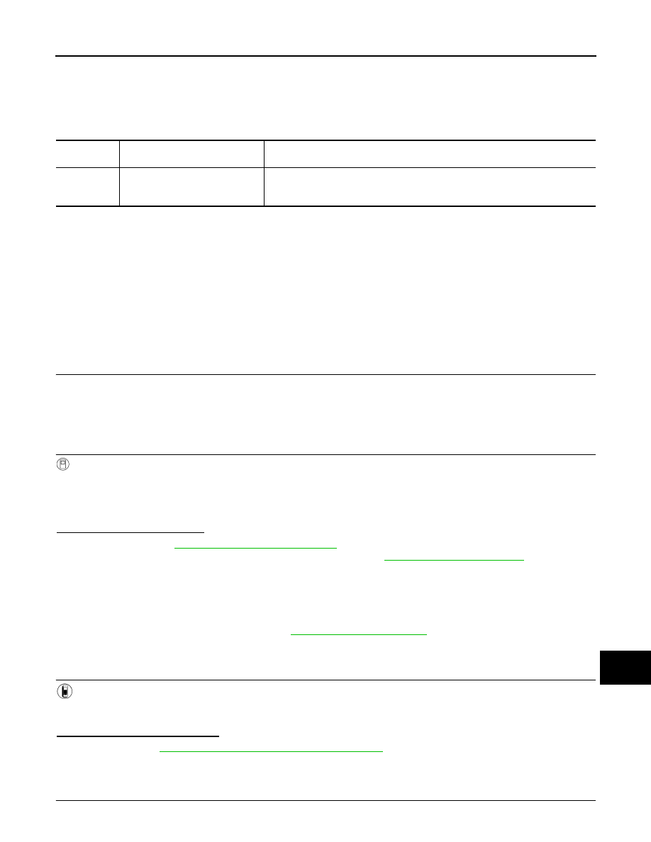
DTC
Display Item
(Trouble diagnosis content)
Malfunction detected condition
U1A35-00
BRAKE CONTROL COMM
(Brake control communication)
A calculated signal value differs between a signal transmitted from the ABS actu-
ator and electric unit (control unit) and a signal received from chassis control mod-
ule via CAN communication.