Nissan Rogue. Manual - part 246


  Index      Nissan     Nissan Rogue (2015 year) - Service and Repair Manual


Search            


Content   ..  244  245  246  247   ..


Nissan Rogue. Manual - part 246


DAS

WARNING SYSTEMS SWITCH CIRCUIT

DAS-155

< DTC/CIRCUIT DIAGNOSIS >

[DRIVER ASSISTANCE SYSTEM]

C

D

E

F

G

H

I

J

K

L

M

B

N

P

A

WARNING SYSTEMS SWITCH CIRCUIT

Diagnosis Procedure

INFOID:0000000011277318

Regarding Wiring Diagram information, refer to 

DAS-52, "Wiring Diagram"

.

1.

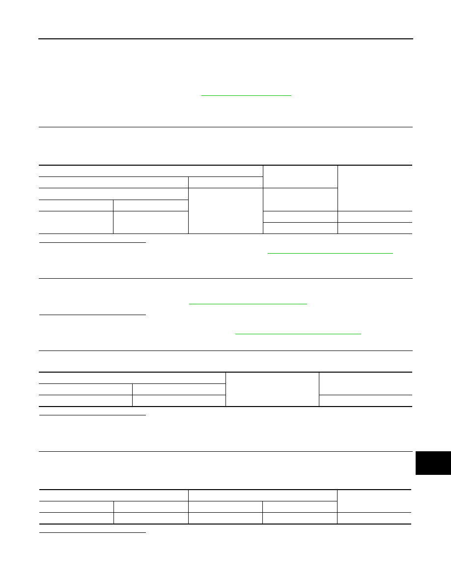
CHECK WARNING SYSTEMS SWITCH SIGNAL INPUT

1. Turn the ignition switch ON.

2. Check voltage between around view monitor control unit harness connector M113 terminal 17 and

ground.

Is the inspection result normal?

YES

>> Replace the around view monitor control unit. Refer to 

DAS-173, "Removal and Installation"

.

NO

>> GO TO 2.

2.

CHECK WARNING SYSTEMS SWITCH

1. Turn ignition switch OFF.

2. Remove warning system switch.

3. Check warning system switch. Refer to 

DAS-156, "Component Inspection"

.

Is the inspection result normal?

YES

>> GO TO 3.

NO

>> Replace the warning system switch. Refer to 

DAS-174, "Removal and Installation"

.

3.

CHECK WARNING SYSTEM SWITCH GROUND CIRCUIT

Check continuity between warning system switch harness connector M253 terminal 8 and ground.

Is the inspection result normal?

YES

>> GO TO 4.

NO

>> Repair harness or connector.

4.

CHECK WARNING SYSTEM SWITCH SIGNAL INPUT CIRCUIT FOR OPEN

1. Disconnect the around view monitor control unit control unit connector.

2. Check continuity between the around view monitor control unit harness connector M113 terminal 17 and

warning system switch harness connector M253 terminal 6.

Is the inspection result normal?

YES

>> GO TO 5.

NO

>> Repair the harnesses or connectors.

Terminals

Condition

Voltage

(Approx.)

(+)

(

−)

AVM control unit

Ground

Warning systems switch

Connector

Terminal

M113

17

Pressed

0 V

Released

Battery voltage

Warning system switch 

Ground

Continuity

Connector

Terminal

M253

8

Yes

Around view monitor control unit

Warning system switch

Continuity

Connector

Terminal

Connector

Terminal

M113

17

M253

6

Yes

DAS-156

< DTC/CIRCUIT DIAGNOSIS >

[DRIVER ASSISTANCE SYSTEM]

WARNING SYSTEMS SWITCH CIRCUIT

5.

CHECK WARNING SYSTEM SWITCH SIGNAL INPUT CIRCUIT FOR SHORT

Check continuity between the around view monitor control unit harness connector M113 terminal 17 and

ground.

Is the inspection result normal?

YES

>> Replace the around view monitor control unit. Refer to 

DAS-173, "Removal and Installation"

.

NO

>> Repair the harnesses or connectors.

Component Inspection

INFOID:0000000011277319

1.

CHECK WARNING SYSTEMS SWITCH

Check continuity of warning system switch.

Is the inspection result normal?

YES

>> Inspection End.

NO

>> Replace the warning system switch. Refer to 

DAS-174, "Removal and Installation"

.

Around view monitor control unit

Ground

Continuity

Connector

Terminal

M113

17

No

Warning system switch

Continuity

Terminal

Condition

6

8

When warning system switch is pressed

Yes

When warning system switch is released

No

DAS

WARNING SYSTEMS ON INDICATOR CIRCUIT

DAS-157

< DTC/CIRCUIT DIAGNOSIS >

[DRIVER ASSISTANCE SYSTEM]

C

D

E

F

G

H

I

J

K

L

M

B

N

P

A

WARNING SYSTEMS ON INDICATOR CIRCUIT

Diagnosis Procedure

INFOID:0000000011277320

Regarding Wiring Diagram information, refer to 

DAS-52, "Wiring Diagram"

.

1.

CHECK WARNING SYSTEM ON INDICATOR POWER SUPPLY CIRCUIT

1. Turn ignition switch OFF.

2. Disconnect warning system switch connector M253.

3. Turn ignition switch ON.

4. Check voltage between warning system switch harness connector M253 terminal 5 and ground.

Is the inspection result normal?

YES

>> GO TO 2.

NO

>> Repair the harness or connector.

2.

CHECK WARNING SYSTEMS ON INDICATOR SIGNAL FOR OPEN

1. Turn ignition switch OFF.

2. Disconnect the around view monitor control unit harness connector M113.

3. Check continuity between the around view monitor control unit harness connector M113 terminal 15 and

warning system switch harness connector M253 terminal 3.

Is the inspection result normal?

YES

>> GO TO 3.

NO

>> Repair the harnesses or connectors.

3.

CHECK WARNING SYSTEMS ON INDICATOR SIGNAL CIRCUIT FOR SHORT

Check continuity between the around view monitor control unit harness connector M113 terminal 15 and

ground.

Is the inspection result normal?

YES

>> GO TO 4.

NO

>> Repair the harnesses or connectors.

4.

CHECK WARNING SYSTEMS ON INDICATOR

Check the warning systems ON indicator. Refer to 

DAS-158, "Component Inspection"

.

Is the inspection result normal?

YES

>> Replace the around view monitor control unit. Refer to 

DAS-173, "Removal and Installation"

.

NO

>> Replace warning systems switch. 

DAS-174, "Removal and Installation"

.

Terminals

Voltage

(Approx.)

(+)

(

−)

Warning system switch

Ground

Connector

Terminal

M253

5

Battery voltage

Around view monitor control unit

Warning system switch

Continuity

Connector

Terminal

Connector

Terminal

M113

15

M253

3

Yes

Around view monitor control unit

Ground

Continuity

Connector

Terminal

M113

15

No

DAS-158

< DTC/CIRCUIT DIAGNOSIS >

[DRIVER ASSISTANCE SYSTEM]

WARNING SYSTEMS ON INDICATOR CIRCUIT

Component Inspection

INFOID:0000000011277321

1.

CHECK WARNING SYSTEMS ON INDICATOR

Apply battery voltage to warning system switch terminals 3 and 5, and then check if the warning systems ON

indicator illuminates.

Is the inspection result normal?

YES

>> Inspection End.

NO

>> Replace the warning systems switch. Refer to 

DAS-174, "Removal and Installation"

.

Warning system switch

Terminals

Condition

Warning system switch ON indicator

(+)

(-)

5

3

When the battery voltage is applied

On

When the battery voltage is not applied

Off


Content   ..  244  245  246  247   ..