Nissan Rogue. Manual - part 216
DAS
HANDLING PRECAUTION
DAS-35
< SYSTEM DESCRIPTION >
[DRIVER ASSISTANCE SYSTEM]
C
D
E
F
G
H
I
J
K
L
M
B
N
P
A
HANDLING PRECAUTION
Precautions for Forward Collision Warning
INFOID:0000000011277187
• The forward collision warning system is designed to warn the driver before a collision but will not avoid a col-
lision. It is the driver's responsibility to stay alert, drive safely and be in control of the vehicle at all times.
• The distance sensor does not detect the following objects:
- Pedestrians, animals, or obstacles in the roadway.
- Oncoming vehicles.
- Crossing vehicles.
• The forward collision warning system does not function when a vehicle ahead is a narrow vehicle, such as a
motorcycle.
• The distance sensor may not detect a vehicle ahead in the following conditions:
- Snow or heavy rain.
- Dirt, ice, snow or other material covering the distance sensor.
- Contamination or foreign materials adhere to the distance sensor area of the front bumper.
- The distance sensor area of the front bumper is temporarily fogged.
- Interference by other radar sources.
- Snow or road spray from traveling vehicles is splashed.
- Driving in a tunnel
• When the distance to the vehicle ahead is too close, the beam of the distance sensor is obstructed.
• The distance sensor may not detect a second vehicle when driving on a steep downhill slope or on roads
with sharp curves.
• Excessive noise will interfere with the warning tone sound, and it may not be heard.
Precautions for Lane Departure Warning
INFOID:0000000011277188
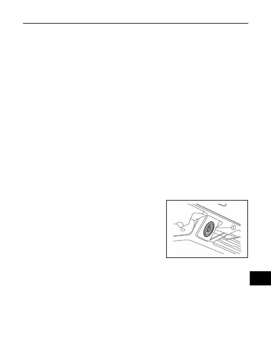
REAR VIEW CAMERA HANDLING
The rear camera unit “1” for the LDW/BSW systems is located above the rear license plate.
To keep the proper operation of the LDW systems and prevent a system malfunction, be sure to observe the
following:
• Always keep the camera lens clean. Be careful not to damage the nozzle of the automatic washer and
blower.
• Do not attach ”license plate accessories” that reflect light.
• Do not strike or damage the areas around the camera unit.
LANE DEPARTURE WARNING (LDW)
• LDW system is only a warning device to inform the driver of a potential unintended lane departure. It will not
steer the vehicle or prevent loss of control. It is the driver’s responsibility to stay alert, drive safely, keep the
vehicle in the traveling lane, and be in control of the vehicle at all times.
• The camera unit may not detect properly under the following conditions:
- When towing a trailer.
- When strong light enters the camera unit. (For example, direct sunlight or headlight from the rear.)
- When ambient light changes instantly. (For example, when the vehicle enters or exits a tunnel or passes
under a bridge.)
• Automatic washer and blower may not be able to secure detection capability when excessive dirt adheres on
the camera lens.
• Excessive noise (e.g. audio system volume, open vehicle window) will interfere with the chime sound, and it
may not be heard.
• The camera unit may not be able to detect properly under the following conditions:
ALOIA0181ZZ