Nissan Rogue. Manual - part 210
DAS
COMPONENT PARTS
DAS-11
< SYSTEM DESCRIPTION >
[DRIVER ASSISTANCE SYSTEM]
C
D
E
F
G
H
I
J
K
L
M
B
N
P
A
SYSTEM DESCRIPTION
COMPONENT PARTS
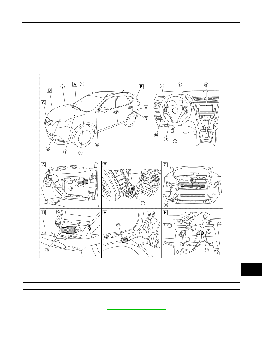
Component Parts Location
INFOID:0000000011277164
A. View with glove box assembly removed B. View with front bumper fascia removed C. View with front bumper fascia removed
D. Rear under body LH
E. View with luggage rear plate removed F.
View with back door finisher removed
ALOIA0233ZZ
No.
Component
Function
1.
Blind spot warning indicator RH
DAS-14, "Blind Spot Warning Indicator LH/RH"
.
2.
ABS actuator and electric unit
(control unit)
Transmits the vehicle speed signal (wheel speed) to around view monitor via CAN commu-
nication.
Refer to
BRC-7, "Component Parts Location"
for detailed installation location.
3.
ECM
• Transmits engine speed signal to around view monitor control unit via CAN communica-
tion.
• Refer to
EC-14, "Component Parts Location"
for detailed installation location.