Content .. 1222 1223 1224 1225 ..
Nissan Rogue. Manual - part 1224
WCS
COMBINATION METER
WCS-25
< ECU DIAGNOSIS INFORMATION >
C
D
E
F
G
H
I
J
K
L
M
B
A
O
P
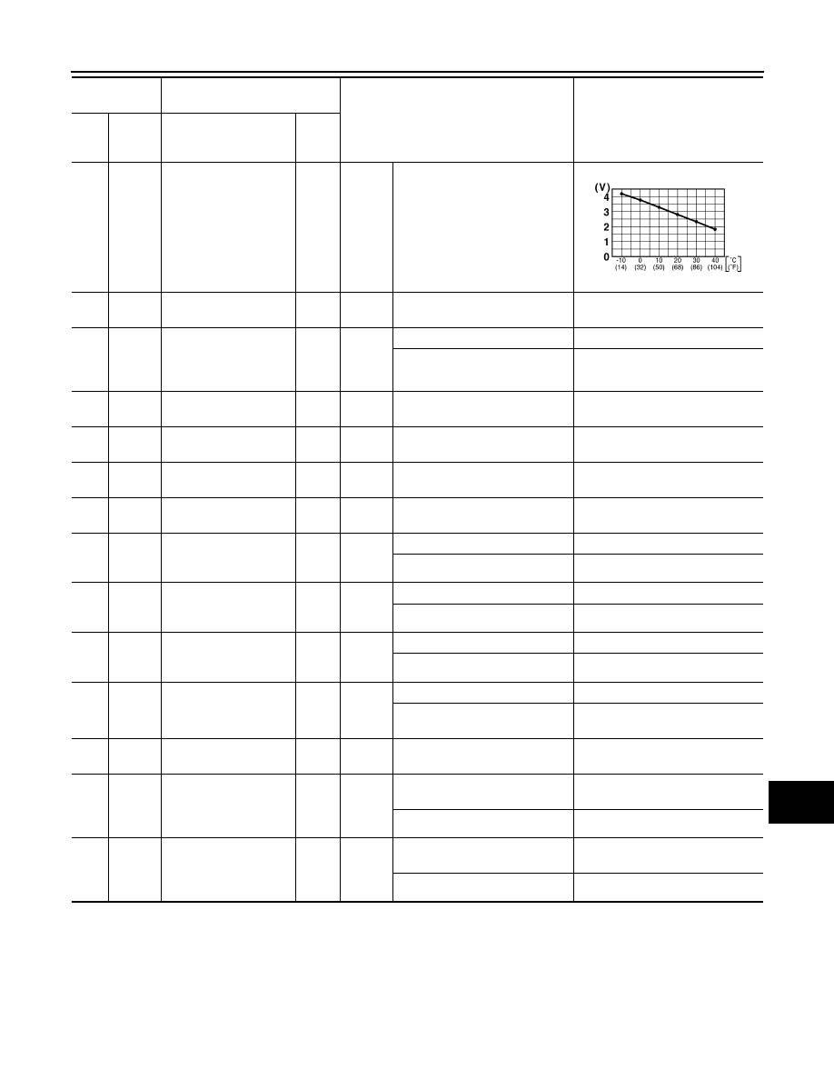
15
(L)
Ground
Ambient sensor signal
Input
Ignition
switch
ON
—
17
(BG)
Ground
Meter control switch
ground
—
—
—
0 V
18
(SB)
Ground Trip/reset signal
Input
Ignition
switch
OFF or
ON
Trip/Reset switch is pressed.
0 V
Other than the above.
5.0 V
20
(Y)
Ground
Ambient sensor ground
—
—
—
0 V
21
(L)
Ground
Steering switch ground
—
—
—
0 V
22
(Y)
Ground
Steering switch output 1
—
—
—
—
23
(GR)
Ground
Steering switch output 2
—
—
—
—
24
(BR)
Ground
Washer fluid level
switch signal
Input
Ignition
switch
ON
Washer fluid level switch ON.
0 V
Washer fluid level switch OFF.
Battery voltage
25
(V)
Ground
Brake fluid level switch
signal
Input
Ignition
switch
ON
Brake fluid level low.
0 V
Brake fluid level normal.
Battery voltage
26
(G)
Ground
Parking brake switch
signal
Input
Ignition
switch
ON
Parking brake applied.
0 V
Parking brake released.
Battery voltage
28
(Y)
Ground
Seat belt buckle switch
signal LH
Input
Ignition
switch
ON
When driver seat belt is fastened.
Battery voltage
When driver seat belt is unfas-
tened.
0 V
29
(R)
Ground
Sport mode switch sig-
nal
—
—
—
—
36
(GR)
Ground
Illumination control
switch signal (+)
Input
Ignition
switch
OFF or
ON
When illumination control switch
(+) is pressed.
0 V
Other than the above.
5.0 V
37
(V)
Ground
Illumination control
switch signal (-)
Input
Ignition
switch
OFF or
ON
When illumination control switch
(-) is pressed.
0 V
Other than the above.
5.0 V
Terminal No.
(Wire color)
Description
Condition
Value
(Approx.)
+
–
Signal name
Input/
Out-
put
JSNIA0014GB