Content .. 1205 1206 1207 1208 ..
Nissan Rogue. Manual - part 1207
TM-200
< REMOVAL AND INSTALLATION >
[CVT: RE0F10D]
KEY INTERLOCK CABLE
KEY INTERLOCK CABLE
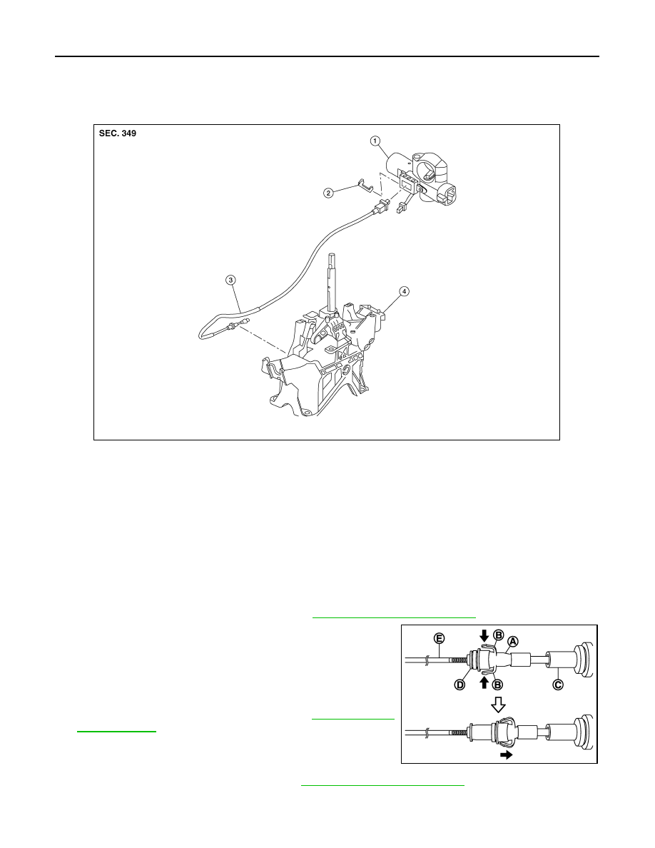
Exploded View
INFOID:0000000011279417
Removal and Installation
INFOID:0000000011279418
REMOVAL
CAUTION:
Always apply the parking brake before performing removal and installation.
1. Move shift selector to the “N” position.
2. Remove the shift selector knob.
3. Move shift selector to the “P” position.
4. Remove the center console assembly. Refer to
IP-19, "Removal and Installation"
5. Press the pawls (B) of the key interlock cable slider (A) while
sliding it in the direction of the casing cap (C), and separate the
adjusting holder (D) and slider (A).
6. Remove the key interlock cable from the shift selector.
7. Remove the steering column covers. Refer to
8. Remove instrument lower panel LH. Refer to
IP-23, "Removal and Installation"
.
1.
Key cylinder
2.
Clip
3.
Key interlock cable
4.
Shift selector assembly
ALDIA0491ZZ
(E)
:Key interlock rod
JSDIA1797ZZ