Content .. 1165 1166 1167 1168 ..
Nissan Rogue. Manual - part 1167
TM-40
< SYSTEM DESCRIPTION >
[CVT: RE0F10D]
SYSTEM
DESCRIPTION
Based on accelerator pedal angle, engine speed, primary pulley speed, and the input speed, the optimum
operating pressure is set to reduce impact of a selector lever operation while shifting from “N” (“P”) to “D” (“R”)
position.
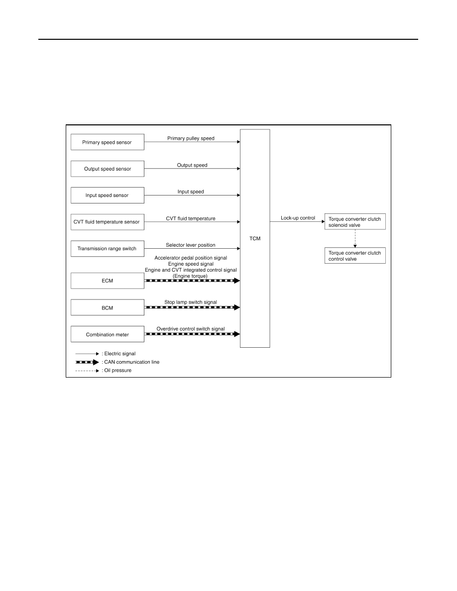
LOCK-UP CONTROL
LOCK-UP CONTROL : System Description
INFOID:0000000011279277
SYSTEM DIAGRAM
DESCRIPTION
• Controls for improvement of the transmission efficiency by engaging the torque converter clutch in the
torque converter and eliminating slip of the converter. Achieves comfortable driving with slip control of the
torque converter clutch.
• The oil pressure feed circuit for the torque converter clutch piston chamber is connected to the torque con-
verter clutch control valve. The torque converter clutch control valve is switched by the torque converter
clutch solenoid valve with the signal from TCM. This controls the oil pressure circuit, which is supplied to the
torque converter clutch piston chamber, to the release side or engagement side.
• If the CVT fluid temperature is low or the vehicle is in fail-safe mode due to malfunction, lock-up control is
prohibited.
Lock-up engagement
In lock-up engagement, the torque converter clutch solenoid valve makes the torque converter clutch control
valve locked up to generate the lock-up apply pressure. This pushes the torque converter clutch piston for
engagement.
Lock-up release condition
In lock-up release, the torque converter clutch solenoid valve makes the torque converter clutch control valve
non-locked up to drain the lock-up apply pressure. This does not engage the torque converter clutch piston.
SPORT MODE CONTROL
JSDIA3783GB