Nissan Rogue. Manual - part 1104


  Index      Nissan     Nissan Rogue (2015 year) - Service and Repair Manual


Search            


Content   ..  1102  1103  1104  1105   ..


Nissan Rogue. Manual - part 1104


NATS ANTENNA AMP.

SEC-195

< REMOVAL AND INSTALLATION >

[WITHOUT INTELLIGENT KEY SYSTEM]

C

D

E

F

G

H

I

J

L

M

A

B

SEC

N

O

P

REMOVAL AND INSTALLATION

NATS ANTENNA AMP.

Removal and Installation

INFOID:0000000011278615

REMOVAL

1. Remove the steering column covers. Refer to 

IP-18, "Removal and Installation"

.

2. Remove instrument lower panel LH. Refer to 

IP-23, "Removal and Installation"

.

3. Remove knee protector. Refer to 

IP-14, "Exploded View"

.

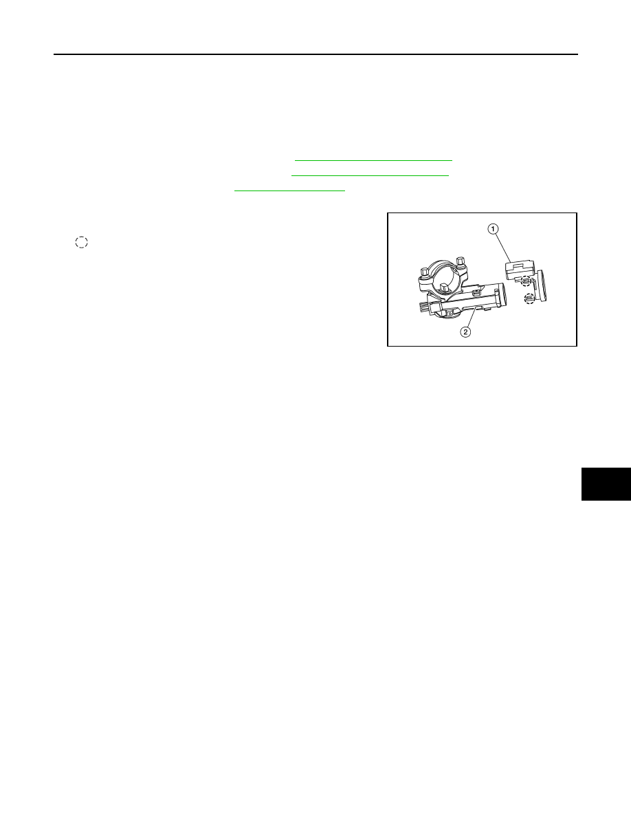
4. Disconnect the harness connector from the NATS antenna amp.
5. Release pawls using suitable tool and remove NATS antenna

amp. (1) from the ignition switch (2).

: Pawl

INSTALLATION

Installation is in the reverse order of removal.

ALKIA3454ZZ

2015 Rogue NAM

SEC-196

< REMOVAL AND INSTALLATION >

[WITHOUT INTELLIGENT KEY SYSTEM]

DONGLE UNIT

DONGLE UNIT

Removal and Installation

INFOID:0000000011301836

REMOVAL

1. Remove instrument panel assembly. Refer to 

IP-14, "INSTRUMENT PANEL ASSEMBLY : Removal and

Installation"

.

2. Disconnect the harness connector from the dongle unit (1).
3. Remove screw (A) and dongle unit (1) from the heating and

cooling unit assembly (2).

INSTALLATION

Installation is in the reverse order of removal.

ALKIA3662ZZ

2015 Rogue NAM

SR-1

RESTRAINTS

C

D

E

F

G

I

J

K

L

M

SECTION 

SR

A

B

SR

N

O

P

CONTENTS

SRS AIRBAG

PRECAUTION ...............................................

2

PRECAUTIONS ...................................................

2

Precaution for Supplemental Restraint System 
(SRS) "AIR BAG" and "SEAT BELT PRE-TEN-
SIONER" .................................................................
..

2

Service ......................................................................

2

Precaution for Work  ..................................................

2

PREPARATION ............................................

4

PREPARATION ...................................................

4

Special Service Tools ................................................

4

BASIC INSPECTION  ....................................

5

COLLISION DIAGNOSIS  ....................................

5

FOR FRONTAL COLLISION  .......................................

5

FOR FRONTAL COLLISION : When SRS is acti-
vated in a collision ...................................................
..

5

FOR FRONTAL COLLISION : When SRS is not 
activated in a collision  .............................................
..

6

FOR SIDE AND ROLLOVER COLLISION ..................

7

FOR SIDE AND ROLLOVER COLLISION : When 
SRS is activated in a collision  .................................
..

7

FOR SIDE AND ROLLOVER COLLISION : When 
SRS is not activated in a collision  ...........................
..

9

REMOVAL AND INSTALLATION ...............

12

DRIVER AIR BAG MODULE ..............................

12

Exploded View  ........................................................

12

Removal and Installation .........................................

12

SPIRAL CABLE  .................................................

15

Exploded View  ........................................................

15

Removal and Installation  .........................................

15

FRONT PASSENGER AIR BAG MODULE  ......

17

Exploded View .........................................................

17

Removal and Installation  .........................................

17

SIDE CURTAIN AIR BAG MODULE  ................

19

Exploded View .........................................................

19

Removal and Installation  .........................................

19

FRONT SIDE AIR BAG MODULE  ....................

21

Removal and Installation  .........................................

21

CRASH ZONE SENSOR ...................................

22

Exploded View .........................................................

22

Removal and Installation  .........................................

22

SIDE AIR BAG (SATELLITE) SENSOR  ...........

23

Exploded View .........................................................

23

Removal and Installation  .........................................

24

AIR BAG DIAGNOSIS SENSOR UNIT .............

26

Exploded View .........................................................

26

Removal and Installation  .........................................

26

FRONT SEAT BELT PRE-TENSIONER ...........

28

Removal and Installation  .........................................

28

FRONT SEAT BELT BUCKLE SWITCH  ..........

29

Removal and Installation  .........................................

29

OCCUPANT CLASSIFICATION SYSTEM  .......

30

Removal and Installation  .........................................

30

FRONT PASSENGER AIR BAG OFF INDICA-
TOR ...................................................................

33

Removal and Installation  .........................................

33

SR-2

< PRECAUTION >

PRECAUTIONS

PRECAUTION

PRECAUTIONS

Precaution for Supplemental Restraint System (SRS) "AIR BAG" and "SEAT BELT 
PRE-TENSIONER"

INFOID:0000000011279746

The Supplemental Restraint System such as “AIR BAG” and “SEAT BELT PRE-TENSIONER”, used along

with a front seat belt, helps to reduce the risk or severity of injury to the driver and front passenger for certain

types of collision. Information necessary to service the system safely is included in the SR and SB section of

this Service Manual.

WARNING:

• To avoid rendering the SRS inoperative, which could increase the risk of personal injury or death in

the event of a collision which would result in air bag inflation, all maintenance must be performed by

an authorized NISSAN/INFINITI dealer.

• Improper maintenance, including incorrect removal and installation of the SRS, can lead to personal

injury caused by unintentional activation of the system. For removal of Spiral Cable and Air Bag

Module, see the SR section.

• Do not use electrical test equipment on any circuit related to the SRS unless instructed to in this

Service Manual. SRS wiring harnesses can be identified by yellow and/or orange harnesses or har-

ness connectors.

PRECAUTIONS WHEN USING POWER TOOLS (AIR OR ELECTRIC) AND HAMMERS

WARNING:

• When working near the Airbag Diagnosis Sensor Unit or other Airbag System sensors with the Igni-

tion ON or engine running, DO NOT use air or electric power tools or strike near the sensor(s) with a

hammer. Heavy vibration could activate the sensor(s) and deploy the air bag(s), possibly causing

serious injury.

• When using air or electric power tools or hammers, always switch the Ignition OFF, disconnect the

battery and wait at least three minutes before performing any service.

Service

INFOID:0000000011279747

• Do not use electrical test equipment to check SRS circuits unless instructed to in this Service Manual.

• Before servicing the SRS, turn ignition switch OFF, disconnect battery negative terminal and wait at least

three minutes.

For approximately three minutes after the cables are removed, it is still possible for the air bag and seat belt

pre-tensioner to deploy. Therefore, do not work on any SRS connectors or wires until at least three minutes

have elapsed.

• Diagnosis sensor unit must always be installed with their arrow marks “

⇐” pointing towards the front of the

vehicle for proper operation. Also check diagnosis sensor unit for cracks, deformities or rust before installa-

tion and replace as required.

• The spiral cable must be aligned in the neutral position since its rotations are limited. Do not turn steering

wheel and column after removal of steering gear.

• Handle air bag module carefully. Always place driver and front passenger air bag modules with the pad side

facing upward and seat mounted front side air bag module standing with the stud bolt side facing down.

• Conduct self-diagnosis to check entire SRS for proper functioning after replacing any components.

• After air bag inflates, the front instrument panel assembly should be replaced if damaged.

• Always replace instrument panel pad following front passenger air bag deployment.

Precaution for Work

INFOID:0000000011279748

• When removing or disassembling each component, be careful not to damage or deform it. If a component

may be subject to interference, be sure to protect it with a shop cloth.

• When removing (disengaging) components with a screwdriver or similar tool, be sure to wrap the component

with a shop cloth or vinyl tape to protect it.

• Protect the removed parts with a shop cloth and prevent them from being dropped.

• Replace a deformed or damaged clip.

• If a part is specified as a non-reusable part, always replace it with a new one.

• Be sure to tighten bolts and nuts securely to the specified torque.

• After installation is complete, be sure to check that each part works properly.


Content   ..  1102  1103  1104  1105   ..