Nissan Rogue. Manual - part 73


  Index      Nissan     Nissan Rogue (2015 year) - Service and Repair Manual


Search            


Content   ..  71  72  73  74   ..


Nissan Rogue. Manual - part 73


AV-284

< BASIC INSPECTION >

[NAVIGATION WITH BOSE]

INSPECTION AND ADJUSTMENT

PREDICTED COURSE LINE CENTER POSITION ADJUSTMENT : Description

INFOID:0000000011276951

Adjust the center position of the predictive course line of the rear view monitor if it is shifted.

PREDICTED COURSE LINE CENTER POSITION ADJUSTMENT : Work Procedure

INFOID:0000000011276952

1.

DRIVING

Drive the vehicle straight ahead 100 m (328.1 ft) or more at a speed of 30 km/h (18.6 MPH) or more.

>> End.

CALIBRATING CAMERA IMAGE (AROUND VIEW MONITOR)
CALIBRATING CAMERA IMAGE (AROUND VIEW MONITOR) : Description

INFOID:0000000011276953

• Calibration must be performed after removing/replacing the cameras, removing parts (e.g. front grille, door

mirror, and others) mounted on the cameras, or replacing the Around view monitor control unit.

• The use of CONSULT is required to perform calibration or writing of calibration results to the Around view

monitor control unit.

• Align the white lines on the road near the vehicle at the boundary of each camera image by this camera cal-

ibration. The white lines far from the vehicle may not be aligned at the boundary of each camera image. The

farther the line, the greater the difference is. 

CALIBRATING CAMERA IMAGE (AROUND VIEW MONITOR) : Work Procedure

INFOID:0000000011276954

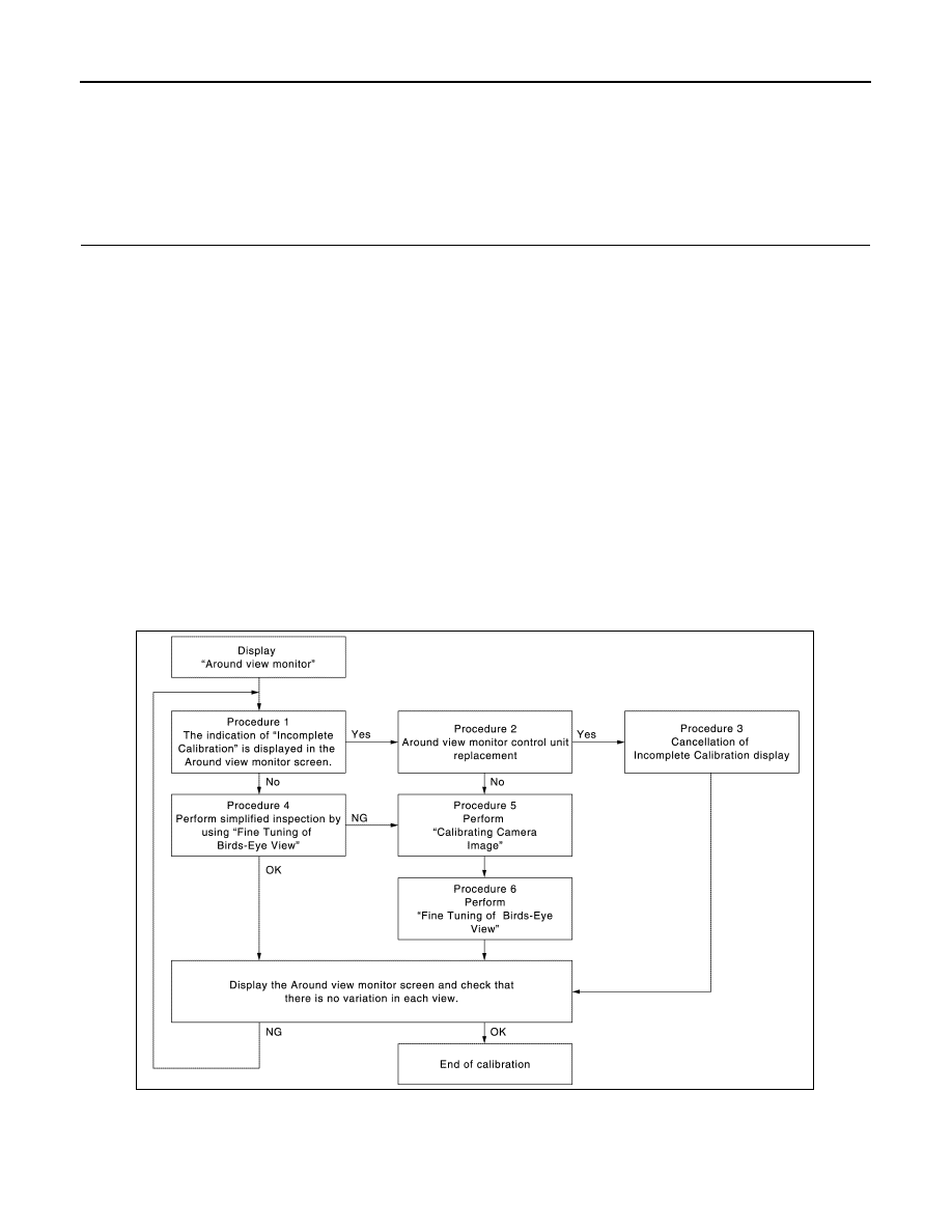
CALIBRATION FLOWCHART

Following the flowchart shown in the figure, perform the calibration. 

NOTE:

JSNIA4210GB

AV

INSPECTION AND ADJUSTMENT

AV-285

< BASIC INSPECTION >

[NAVIGATION WITH BOSE]

C

D

E

F

G

H

I

J

K

L

M

B

A

O

P

View in the incomplete calibration state is indicated by “

” on the

around view monitor.

CALIBRATION PROCEDURE

1.

AROUND VIEW MONITOR SCREEN CONFIRMATION

Check that there is no indication of “Incomplete calibration”.
Is the “Incomplete calibration” display visible?

YES

>> GO TO 2.

NO

>> GO TO 4.

2.

CHECK THAT AROUND VIEW MONITOR CONTROL UNIT IS REPLACED

Check that the around view monitor control unit is replaced.
Is the around view monitor control unit replaced?

YES

>> GO TO 3.

NO

>> GO TO 5.

3.

CANCEL THE INDICATION OF INCOMPLETE CALIBRATION (PERFORM THIS ONLY AFTER REPLAC-

ING AROUND VIEW MONITOR CONTROL UNIT.)

CONSULT work support

1. On the CONSULT screen, touch “CALIBRATING CAMERA IMAGE (FRONT CAMERA)”, “CALIBRATING

CAMERA IMAGE (PASS-SIDE CAMERA)”, “CALIBRATING CAMERA IMAGE (DR-SIDE CAMERA)”, or

“CALIBRATING CAMERA IMAGE (REAR CAMERA)” to accept the selection.

NOTE:

To cancel the indication of Incomplete calibration, select items based on the target camera. 

2. On the adjustment screen of each camera, touch “APPLY” but-

ton. After this, touch “OK” button.

CAUTION:

• Never perform operations other than those mentioned

above.

• Never perform “Initialize Camera Image Calibration”. 

3. Display the around view monitor screen to check that there is no

errors, such as deviations among the camera images.

Is there a malfunction?

YES

>> Calibration End.

NO

>> GO TO 1.

4.

PERFORM SIMPLIFIED CONFIRMATION/ADJUSTMENT BY “FINE TUNING OF BIRDS-EYE VIEW”

1. Put target line 1 on the ground beside each axle using packing tape, etc. 

2. Put target lines 2 equal to the vehicle total length + approximately 1.0 m (39.3 in) from the vehicle side

(right and left) at approximately 30 cm (11.8 in) away from the vehicle (make the line as parallel with the

vehicle as possible). 

AWNIA2590GB

AWNIA2590GB

JSNIA4212ZZ

AV-286

< BASIC INSPECTION >

[NAVIGATION WITH BOSE]

INSPECTION AND ADJUSTMENT

Preparation of simplified target line

3.

CONSULT work support

Touch “FINE TUNING OF BIRDS-EYE VIEW” on the CONSULT screen.

4. On the CONSULT screen, touch “SELECT” button to select right or left camera and perform camera cali-

bration as instructed below:

-

If the marker on the screen deviates from Target line 1, touch “AXIS X” button and “AXIS Y” button to

adjust so that the marker is placed on the Target line 1.   

-

If Target line 2 is misaligned among the cameras, adjust each camera image to bring Target line 2 into a

straight line.

CAUTION:

Never adjust the front camera and rear camera. Only adjust the right and left cameras. 

Simplified target line adjustment method

5. Adjust right and left cameras. Touch "APPLY" on the CONSULT screen to display adjustment results. 

6. After adjusting right and left cameras, check that the marker is properly placed on the screen and there is

no deviation in Target line 1.    

NOTE:

• It can be initialized to the NISSAN factory default condition with “Initialize Camera Image Calibration”. 

• The adjustment value is cancelled on this mode by performing “Initialize Camera Image Calibration”. 

JSNIA0927ZZ

1.

Target lines 1

2.

Target lines 2

A.

Approx. 30 cm (11.8 in)

B.

Approx. 1.0 m (39.3 in)

JSNIA0929ZZ

1.

Target lines 1

2.

Target lines 2

3.

Marker for target line 1

4.

Boundary between cameras

5.

Crosshairs cursor (mark indicated 
the selected camera)

A.

Adjustment method for target lines 1 
(right)

B.

Adjustment method for target lines 2 
(right)

AV

INSPECTION AND ADJUSTMENT

AV-287

< BASIC INSPECTION >

[NAVIGATION WITH BOSE]

C

D

E

F

G

H

I

J

K

L

M

B

A

O

P

Is the difference corrected?

YES

>> On the CONSULT screen, touch “OK” button to complete writing to the around view monitor con-

trol unit.

NO

>> GO TO 5.

5.

PERFORM “CALIBRATING CAMERA IMAGE”

Preparation of target line

1. Hang a string with a weight as shown in the figure. Put the points FM0, RM0 (mark) on the ground at the

center of the vehicle front end and rear end with white packing tape or a pen. 

2. Route the vinyl string under the vehicle, and then pull and fix it on the point approximately 1.0 m (39.9 in)

to the front and rear of the vehicle through the points FM0 and RM0 using packing tape. 

Target line preparation procedure 1

3. Put the points FM and RM (mark) 75 cm (29.5 in) from the points FM0 and RM0 individually. 

4. Route the vinyl string through the points FM and RM using a triangle scale, and then fix it at approximately

1.5 m (59 in) on both sides with packing tape. 

5. Put the points FL, FR, RL, and RR (mark) to both right and left [vehicle width / 2 + 30 cm (11.8 in)] from the

points FM and RM. 

Target line preparation procedure 2

AWNIA3140ZZ

1.

Thread

2.

Weight

3.

Point FM0 (mark)

4.

Point RM0 (mark)

5.

Packing tape (to fix the vinyl string)

6.

Vinyl string

JSNIA0921ZZ

1.

Point FM

2.

Point RM

3.

Triangle scale

4.

Point FL (mark)

5.

Point FR (mark)

6.

Point RL (mark)


Content   ..  71  72  73  74   ..