Nissan Rogue. Manual - part 27


  Index      Nissan     Nissan Rogue (2015 year) - Service and Repair Manual


Search            


Content   ..  25  26  27  28   ..


Nissan Rogue. Manual - part 27


AV-100

< ECU DIAGNOSIS INFORMATION >

[NAVIGATION WITHOUT BOSE]

AV CONTROL UNIT

9

 (V)

Ground Illumination control signal

Input

ON

Headlamps ON

Battery voltage

11

(G)

12

(V)

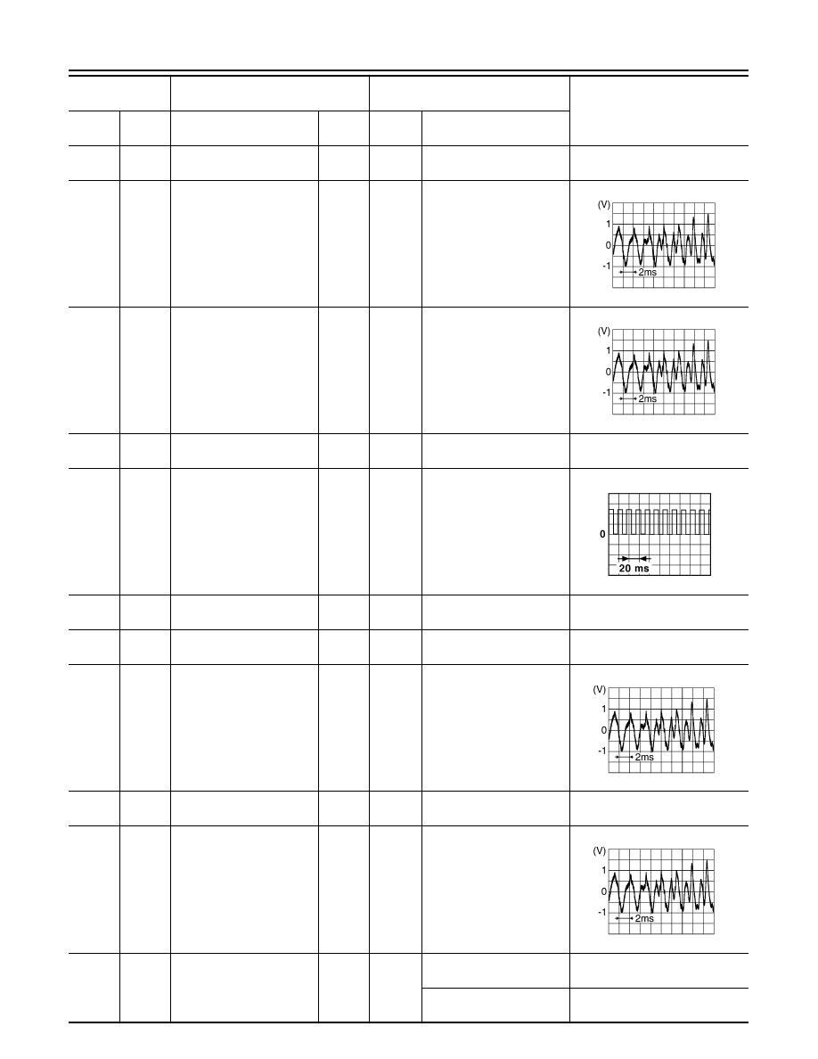
Sound signal front speaker 
and tweeter RH

Output

ON

Sound output

13

(LG)

14

(Y)

Sound signal rear speaker 
RH

Output

ON

Sound output

17

(R)

CAN  (L)

Input/

Output

18

(G)

Ground Vehicle speed signal

Input

ON

When vehicle speed is ap-
prox. 40 km/h (25 MPH)

19

(L)

Ground Battery power supply

Input

OFF

Battery voltage

20

(B)

Ground Ground

ON

0 V

21

(G)

Ground AUX jack audio signal RH

Input

ON

Received audio signal 
(AUX input)

22

(Y)

Ground

AUX ground

ON

0V

23

(L)

Ground AUX jack audio signal LH

Input

ON

Received audio signal 
(AUX input)

25

(BR)

Ground Reverse signal

Input

ON

Selector lever in R (re-
verse)

Battery voltage

Selector lever in any posi-
tion other than R (reverse)

0 V

Terminal

(Wire color)

Description

Condition

Reference value

(Approx.)

+

Signal name

Input/

Output

Ignition 

switch

Operation

SKIB3609E

SKIB3609E

JSNIA0012GB

SKIB3609E

SKIB3609E

AV

AV CONTROL UNIT

AV-101

< ECU DIAGNOSIS INFORMATION >

[NAVIGATION WITHOUT BOSE]

C

D

E

F

G

H

I

J

K

L

M

B

A

O

P

30

(BG)

MR output

Output

31

(SB)

AV communication (H)

Input/

Output

32

(LG)

AV communication (L)

Input/

Output

34

(W)

36

(Shield)

Microphone signal

Input

ON

While speaking into micro-
phone. 

35

(B)

MIC VCC

Input

ON

37

(Shield)

AUX signal shield

38

(SB)

AV communication (H)

Input/

Output

39

(LG)

AV communication (L)

Input/

Output

40

(LG)

Ground Ignition power supply

Input

ON

Battery voltage

41

(W)

Ground Camera image signal

Input

ON

When camera image is dis-
played

42

(Shield)

Camera image signal 
shield

45

(R)

V BUS signal

46

(W)

USB D

− signal

47

(G)

USB + signal

49

(B)

USB ground

50

(Shield)

USB shield

51

(B)

Ground Antenna amp. ON signal

Output

ON

AV control unit ON, FM-AM 
selected.

Battery voltage

52

(B)

Ground AM-FM main antenna

Input

ON

AV control unit ON, FM-AM 
selected.

5.0 V

53

(Shield)

Antenna amp. Shield

Terminal

(Wire color)

Description

Condition

Reference value

(Approx.)

+

Signal name

Input/

Output

Ignition 

switch

Operation

SKIB3609E

SKIB2251J

AV-102

< ECU DIAGNOSIS INFORMATION >

[NAVIGATION WITHOUT BOSE]

AV CONTROL UNIT

DTC Index

INFOID:0000000011276802

56

(B)

Ground Satellite antenna signal

Input

ON

AV control unit ON, SXM 
selected.

5.0 V

57

(Shield)

Satellite antenna shield

58

(B)

Ground GPS antenna signal

Input

ON

AV control unit ON, NAV se-
lected.

5.0 V

59

(Shield)

GPS antenna shield

Terminal

(Wire color)

Description

Condition

Reference value

(Approx.)

+

Signal name

Input/

Output

Ignition 

switch

Operation

CONSULT Display

Reference Page

U1000: CAN COMM CIRCUIT

AV-142, "AV CONTROL UNIT : DTC Logic"

U1010: CONTROL UNIT (CAN)

AV-143, "AV CONTROL UNIT : DTC Logic"

U1217: BLUETOOTH MODULE

AV-152, "DTC Logic"

U1229: iPod CERTIFICATION

AV-153, "DTC Logic"

U122F: Digital broadcasting connection error

AV-154, "DTC Logic"

U1244: GPS ANTENNA CONN

AV-156, "DTC Logic"

U1258: SXM ANTENNA CONN

AV-157, "DTC Logic"

U1263: USB OVERCURRENT

AV-158, "DTC Logic"

U12AA: Configuration Error

AV-159, "DTC Logic"

U12AB: FM Antenna error

AV-160, "DTC Logic"

U12AC: Display Temperature too High

AV-161, "DTC Logic"

U12AD: ECU Temperature too High

AV-162, "DTC Logic"

U12AE: Internal Amplifier temperature Warning

AV-163, "DTC Logic"

U12AF: CD Mechanism Temperature Warning

AV-164, "DTC Logic"

U12B0: Supply Voltage Goes below 9V > 20s

AV-165, "DTC Logic"

U12B1: Supply Voltage Goes High > 16V for 20s

AV-166, "DTC Logic"

U1300: AV COMM CIRCUIT

AV-167, "DTC Logic"

U1310: CONTROL UNIT(AV)

AV-171, "DTC Logic"

AV

AROUND VIEW MONITOR CONTROL UNIT

AV-103

< ECU DIAGNOSIS INFORMATION >

[NAVIGATION WITHOUT BOSE]

C

D

E

F

G

H

I

J

K

L

M

B

A

O

P

AROUND VIEW MONITOR CONTROL UNIT

Reference Value

INFOID:0000000011276805

VALUES ON THE DIAGNOSIS TOOL

Monitor Item

Condition

Value/Status

CAMERA OFF SIGNAL

CAMERA switch ON.

Off

CAMERA switch OFF.

On

CAMERA SWITCH SIGNAL

CAMERA switch OFF.

Off

CAMERA switch ON.

On

DR-SIDE CAMERA IMAGE SIG

Side camera LH inoperative.

NG

Side camera LH operative.

OK

ILL

Illumination is ON 

On

Illumination is OFF 

Off

ITS SW 1

ITS switch is pressed

On

ITS switch is not pressed

Off

ITS SW 1 IND

Indicator of ITS switch 1 is lighting

On

Indicator of ITS switch 1 is not lighting

Off

ITS SW 2

For this vehicle, the displaying is fixed

No SET

ITS SW 2 IND

For this vehicle, the displaying is fixed

No SET

F-CAMERA IMAGE SIG

Front camera inoperative.

NG

Front camera operative.

OK

PA-SIDE CAMERA IMAGE SIG

Side camera RH inoperative.

NG

Side camera RH operative.

OK

PUMP COMM STATUS

Pump communication signal is received

On

Pump communication signal is not received

Off

R-CAMERA COMM STATUS

Rear camera serial status is OK

OK

Rear camera serial status is not OK

NG

R-CAMERA COMM LINE

Rear camera serial communication signal is received 

OK

Rear camera serial communication signal is not received 

NG

REAR CAMERA IMAGE SIGNAL

Rear camera LH inoperative.

NG

Rear camera LH operative.

OK

REVERSE SIGNAL

When selector lever is in any position other than R (reverse).

Off

When selector lever in R (reverse).

On

ST ANGLE SENSOR SIGNAL

Around view monitor control unit is not receiving steering angle 
sensor signal.

Off

Around view monitor control unit is receiving steering angle sen-
sor signal.

On

ST ANGLE SENSOR TYPE

Steering angle sensor type.

Absolute

ST GEAR RATIO TYPE

Steering gear ratio type.

Type O

STEERING POSITION

Left hand drive vehicle.

LHD

Right hand drive vehicle.

RHD

TURN SIGNAL

Turn signal left is received

Left

Turn signal neutral is received

N

Turn signal right is received

Right

VEHICLE SPEED SIGNAL

While driving, equivalent to speedometer reading

mph, km/h


Content   ..  25  26  27  28   ..