Nissan Rogue. Manual - part 24


  Index      Nissan     Nissan Rogue (2015 year) - Service and Repair Manual


Search            


Content   ..  22  23  24  25   ..


Nissan Rogue. Manual - part 24


AV-88

< SYSTEM DESCRIPTION >

[NAVIGATION WITHOUT BOSE]

SYSTEM

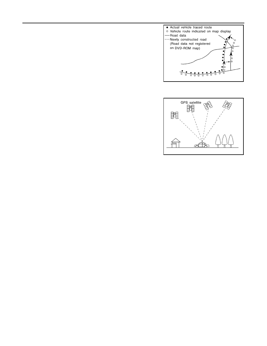
• Map-matching does not function correctly when a road on which

the vehicle is driving is new and not recorded in the map SD-card,

or when road pattern stored in the map data and the actual road

pattern are different due to repair.

The map-matching function may find another road and position the

vehicle mark on it when driving on a road not present in the map.

Then, the vehicle mark may change to it when the correct road is

detected.

• Effective range for comparing the vehicle position and travel direc-

tion calculated by the distance and direction with the road data

read from the map SD-card is limited. Therefore, correction by

map-matching is not possible when there is an excessive gap

between current vehicle position and the position on the map.

GPS (Global Positioning System)

GPS (Global Positioning System) is developed for and is controlled

by the US Department of Defense. The system utilizes GPS satel-

lites (NAVSTAR), transmitting out radio waves while flying on an orbit

around the earth at an altitude of approximately 21,000 km (13,049

mile).

The receiver calculates the travel position in three dimensions (lati-

tude/longitude/altitude) according to the time lag of the radio waves

that four or more GPS satellites transmit (three-dimensional position-

ing). The GPS receiver calculates the travel position in two dimen-

sions (latitude/longitude) with the previous altitude data if the GPS

receiver receives only three radio waves (two-dimensional position-

ing). GPS position correction is not performed while stopping the

vehicle.

Accuracy of the GPS will deteriorate under the following conditions:

• In two-dimensional positioning, GPS accuracy will deteriorate when altitude of the vehicle position changes.

• The position of GPS satellite affects GPS detection precision. The position detection may not be precisely

performed.

• The position detection is not performed if GPS receiver does not receive radio waves from GPS satellites.

(Inside a tunnel, parking in a building, under an elevated highway etc.) GPS receiver may not receive radio

waves from GPS satellites if any object is placed on the GPS antenna.

NOTE:

• The detection result has an error of approximately 10 m (32.81 ft) even with a high-precision three dimen-

sional positioning.

• There may be cases when the accuracy is lowered and radio waves are stopped intentionally because the

GPS satellite signal is controlled by the US trace control center.

USB INTERFACE

• iPod

®

 or music files in USB memory can be played. 

• Sound signals are transmitted from USB interface to the AV control unit and output to each speaker.
• iPod

®

 is recharged when connected to USB interface.

AUX IN JACK

• Sound can be output from an external device by connecting a device to the AUX in jack.

• AUX sound signals are transmitted to each speaker via AV control unit.

SPEED SENSITIVE VOLUME SYSTEM

• Volume level of this system goes up and down automatically in proportion to the vehicle speed.

• The control level can be selected by the customer.

HANDS-FREE PHONE SYSTEM

• Bluetooth

®

 control is built into AV control unit.

• The connection between cellular phone and AV control unit is performed with Bluetooth

®

 communication.

• The voice guidance signal is input from the AV control unit and output to the front speakers when operating

the cellular phone.

When A Call Is Originated

SKIA0613E

SEL526V

AV

SYSTEM

AV-89

< SYSTEM DESCRIPTION >

[NAVIGATION WITHOUT BOSE]

C

D

E

F

G

H

I

J

K

L

M

B

A

O

P

• Spoken voice sound output from the microphone (microphone signal) is input to AV control unit. 
• AV control unit outputs to cellular phone with Bluetooth

®

 communication as a TEL voice signal. 

• Voice sound is then heard at the other party.

When Receiving A Call

• Voice sound is input to own cellular phone from the other party. 
• TEL voice signal is input to AV control unit by establishing Bluetooth

®

 communication from cellular phone,

and the signal is output to front speakers.

AROUND VIEW MONITOR FUNCTION

• This system is equipped with wide-angle cameras on the front, rear and right and left door mirrors.

• Images from front view, rear view, front-side view (RH side), and birds-eye view are displayed to monitor the

vehicle surroundings. 

• Around view monitor control unit expands the image received from each camera to create each view. 

• In front view and rear view, the vehicle width, distance lines and predictive course lines are displayed.

• In front-side view, the vehicle distance guiding line and vehicle width guiding line are displayed. 

• Birds-eye view converts the images from the cameras into an overhead view and displays the status of the

vehicle on the display. The vehicle icon that is displayed in the birds-eye view is depicted by the around view

monitor control unit. 

Display

The around view monitor combines and displays travel direction view (front or rear), front-side view and birds-

eye view.

Operation

• The around view monitor operates by pressing the CAMERA switch on the AV control unit or by shifting the

selector lever to the R (reverse) position. 

• When the selector lever is in any position other than R (reverse) and the CAMERA switch is pressed, the

screen displays front travel direction view and birds-eye view. Pressing the CAMERA switch again changes

birds-eye view to front-side view

• When the selector lever is placed in R (reverse), the screen displays rear travel direction view and birds-eye

view. Pressing the CAMERA switch changes birds-eye view to front-side view

• In birds-eye view, the blind spot area is displayed in black to show the border of the camera images. In addi-

tion, red fixed lines are displayed in the 4 corners of the vehicle icon. After pressing the CAMERA switch for

the first time or placing the selector lever in R (reverse) for the first time, the blind spot area is highlighted in

yellow for 3 seconds and the red fixed lines blink five times.

• With the selector lever in any position other than R (reverse), the around view monitor screen display is can-

celled 3 minutes after pressing the CAMERA switch. The screen returns to the AV control unit display.

• With the selector lever in R (reverse) position, the around view monitor screen display remains on con-

stantly. To return to the AV control unit display, place the selector lever is in any position other than R

(reverse).

• If camera image calibration is incomplete, the applicable camera position is indicated as an error on the

birds-eye view display.

JSNIA3982GB

AV-90

< SYSTEM DESCRIPTION >

[NAVIGATION WITHOUT BOSE]

SYSTEM

NOTE:

Calibration is necessary when replacing each camera or when replacing around view monitor control unit.

Around view monitor screen transition

Front View

• The front view image improves the visibility of obstacles in front of the vehicle and assists driving by display-

ing images from birds-eye view and front-side view.

• The front view image displays the vehicle width guiding line and vehicle distance guiding line, in addition to

the predictive course line according to the steering angle.

• If the steering angle is within approximately 90 degrees, the predictive course lines on the left/right side are

displayed. If the steering angle exceeds approximately 90 degrees, only the predictive course line on the

outside is displayed (opposite side of steering direction).

• The around view monitor control unit receives the steering angle signal from steering angle sensor via CAN

communication, and controls the direction and distance of the predictive course line.

• ON/OFF setting of predictive course line can be performed using CONSULT.

JSNIA4607GB

AV

SYSTEM

AV-91

< SYSTEM DESCRIPTION >

[NAVIGATION WITHOUT BOSE]

C

D

E

F

G

H

I

J

K

L

M

B

A

O

P

Front view guiding lines

Rear View

• The rear view image improves the visibility of obstacles in the rear of the vehicle and assists backing and

parking by displaying images from birds-eye view and front side view.

• The rear view image displays the vehicle width guiding line and vehicle distance guiding line, in addition to

the predictive course line according to the steering angle.

NOTE:

The predictive course line is not displayed at the steering neutral position.

• The around view monitor control unit receives the steering angle signal from steering angle sensor via CAN

communication, and controls the direction and distance of the predictive course line.

• ON/OFF setting of predictive course line can be performed using CONSULT.

Rear view guiding lines

Front-Side View

• The front-side view image improves the visibility of obstacles in the front RH side of the vehicle and assists

backing and parking.

• The front-side view image displays the vehicle distance guiding line and vehicle width guiding line. 

JSNIA0770GB

JSNIA4567GB


Content   ..  22  23  24  25   ..