Nissan Rogue. Manual - part 23


  Index      Nissan     Nissan Rogue (2015 year) - Service and Repair Manual


Search            


Content   ..  21  22  23  24   ..


Nissan Rogue. Manual - part 23


AV-84

< SYSTEM DESCRIPTION >

[NAVIGATION WITHOUT BOSE]

COMPONENT PARTS

Steering Angle Sensor

INFOID:0000000011276791

• Steering sensor is installed to the spiral cable. 

• Steering angle sends the steering signal necessary for predictive

course line via CAN communication. 

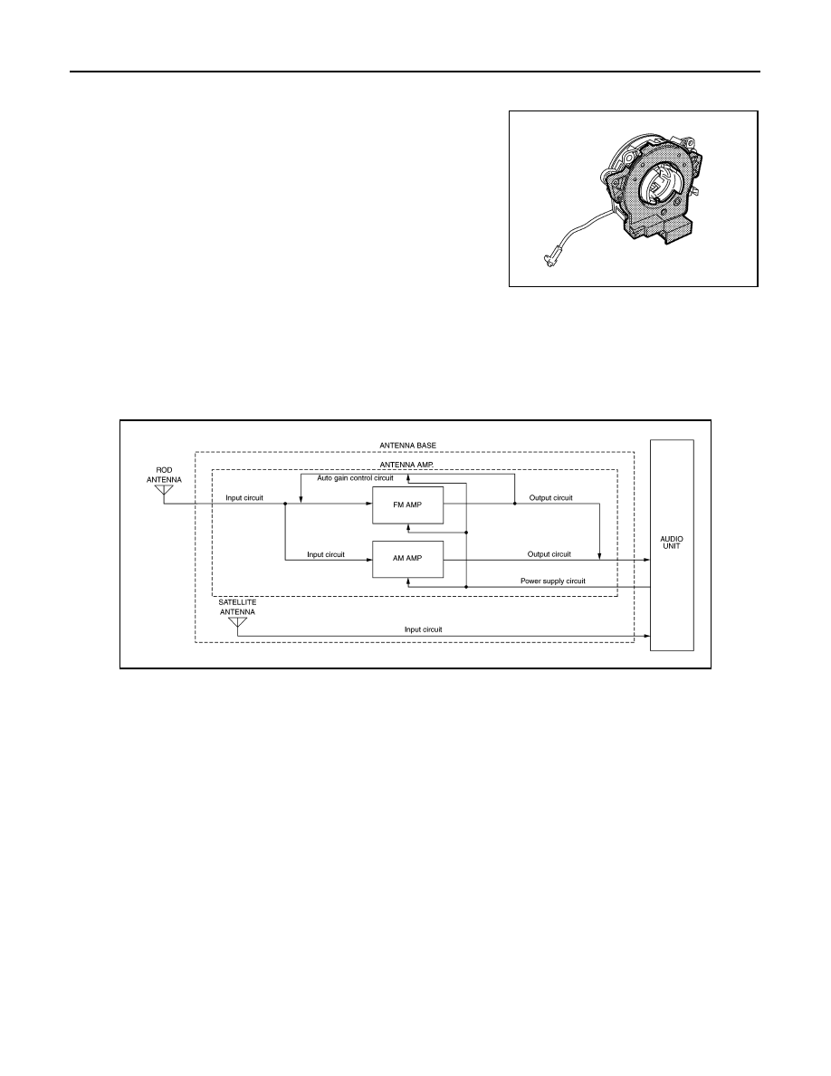
Rod Antenna, Antenna Amp., Satellite Antenna and Antenna Feeder

INFOID:0000000011276792

RADIO ANTENNA AND SATELLITE ANTENNA

AM/FM radio rod antenna, antenna base and satellite antenna are located on the rear of the roof. The antenna

amp. and satellite antenna are built into the antenna base.

ANTENNA FEEDER LAYOUT

JSNIA1571ZZ

AWNIA3133GB

AV

COMPONENT PARTS

AV-85

< SYSTEM DESCRIPTION >

[NAVIGATION WITHOUT BOSE]

C

D

E

F

G

H

I

J

K

L

M

B

A

O

P

GPS Antenna

INFOID:0000000011276793

• GPS antenna is installed in the instrument panel, behind the com-

bination meter.

• Power is supplied from the AV control unit.

SD Card

INFOID:0000000011276794

• Map data is memorized in the SD card.

• Map data is sent to the AV control unit from the SD slot.

1.

Antenna base (antenna amp. and 
satellite antenna)

2.

Rod Antenna

3.

M503

4.

M502

5.

M130, M501

6.

M129, M500

7.

M142

8.

M139

ALNIA1595ZZ

JSNIA3303ZZ

AV-86

< SYSTEM DESCRIPTION >

[NAVIGATION WITHOUT BOSE]

SYSTEM

SYSTEM

System Description

INFOID:0000000011276795

SYSTEM DIAGRAM

AUDIO SYSTEM

The audio system consists of the following component:

• AV control unit

• Front tweeters

• Front door speakers

• Rear door speakers

• USB interface

• AUX in jack

• Steering switches

• Antenna base (rod antenna, antenna amp. and satellite antenna)

When the audio system is on, AM/FM signals received by the rod antenna are amplified by the antenna amp.

and sent to the AV control unit. The AV control unit then sends audio signals to the front tweeters, front door

speakers and rear door speakers.

Refer to Owner's Manual for audio system operating instructions.

NAVIGATION SYSTEM

Description

• The navigation system can be operated by control panel of the AV control unit and display (touch panel) of

the AV control unit.

• Guide sound during the operation of the navigation system is output from AV control unit to front tweeters.

• AV control unit calculates the vehicle location based on the signals from GYRO (angle speed sensor), vehi-

cle sensor, and GPS satellite, as well as the map data from map SD-card. The vehicle location is displayed

on the AV control unit.

POSITION DETECTION PRINCIPLE

AWNIA3350GB

AV

SYSTEM

AV-87

< SYSTEM DESCRIPTION >

[NAVIGATION WITHOUT BOSE]

C

D

E

F

G

H

I

J

K

L

M

B

A

O

P

The navigation system periodically calculates the vehicle's current position according to the following three

signals:

• Travel distance of the vehicle as determined by the vehicle speed sensor

• Turning angle of the vehicle as determined by the gyroscope (angular velocity sensor)

• Direction of vehicle travel as determined by the GPS antenna (GPS information)

The current position of the vehicle is then identified by comparing the calculated vehicle position with map data

read from the map SD-card (map-matching), and indicated on the screen as a vehicle mark. More accurate

data is judged and used by comparing vehicle position detection results found by the GPS with the result by

map-matching.

The current vehicle position will be calculated by detecting the dis-

tance the vehicle moved from the previous calculation point and its

direction.

• Travel distance

Travel distance calculations are based on the vehicle speed sen-

sor input signal. Therefore, the calculation may become incorrect

as the tires wear down. To prevent this, an automatic distance cor-

rection function has been adopted.

• Travel direction

Change in the travel direction of the vehicle is calculated by a gyro-

scope (angular velocity sensor) and a GPS antenna (GPS informa-

tion). They have both advantages and disadvantages.

More accurate traveling direction is detected because priorities are set for the signals from these two

devices according to the situation.

MAP-MATCHING

Map-matching compares a current location detected by the method

in the “Location Detection Principle” with a road map data from map

SD-card.

NOTE:

The road map data is based on data stored in the map SD-card.

The vehicle position may not be corrected under the following circumstances and after driving for a certain

time when GPS information is difficult to receive. In this case, the vehicle mark on the display must be cor-

rected manually:

• In map-matching, alternative routes to reach the destination will be

shown and prioritized, after the road on which the vehicle is cur-

rently driven has been judged and the vehicle mark has been repo-

sitioned.

Alternative routes will be shown in different order of priority, and

the incorrect road can be avoided if there is an error in distance

and/or direction.

Routes are of the same priority if two roads are running in parallel.

Therefore, the vehicle mark may appear on either of them alter-

nately, depending on maneuvering of the steering wheel and con-

figuration of the road.

SEL684V

Type

Advantage

Disadvantage

Gyroscope
(angular velocity sensor)

Can detect the vehicle's turning angle quite 
accurately.

Direction errors may accumulate when vehicle is 
driven for long distances without stopping.

GPS antenna
(GPS information)

Can detect the vehicle's travel direction 
(North/South/East/West).

Correct direction cannot be detected when vehicle 
speed is low.

SEL685V

SEL686V


Content   ..  21  22  23  24   ..