Nissan Maxima. Manual - part 976
SUNROOF SYSTEM
RF-77
< SYSTEM DESCRIPTION >
[WITH DUAL PANEL SUNROOF]
C
D
E
F
G
H
I
J
L
M
A
B
RF
N
O
P
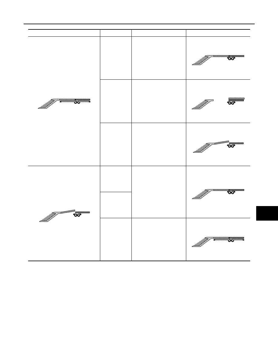
Before Operation
Switch condition Roof and sunshade operation
After Operation
OPEN: 1st
Open the shade
OPEN: 2nd
Open the glass and shade
(AUTO)
PUSH
Tilt up and open the shade at
the same time
PUSH
Tilt down
CLOSE: 1st
CLOSE: 2nd
Tilt down and close the shade
at the same time (AUTO)
JMKIA1885ZZ
JMKIA1884ZZ
JMKIA1887ZZ
JMKIA1886ZZ
JMKIA1886ZZ
JMKIA1884ZZ
JMKIA1885ZZ