Nissan Maxima. Manual - part 890


  Index      Nissan     Nissan Maxima (2009-2014 year) - Service and Repair Manual


Search            


Content   ..  888  889  890  891   ..


Nissan Maxima. Manual - part 890


PCS-40

< SYSTEM DESCRIPTION >

[POWER DISTRIBUTION SYSTEM]

POWER DISTRIBUTION SYSTEM

*1: When the CVT selector lever position is N position, the engine start condition is different according to the vehicle speed.
• At vehicle speed of 4 km/h (2 MPH) or less, the engine can start only when the brake pedal is depressed.
• At vehicle speed of 4 km/h (2 MPH) or more, the engine can start even if the brake pedal is not depressed. (It is the same as “Engine

stall return operation while driving”.)

*2: When the CVT selector lever position is in any position other than P position and when the vehicle speed is 5 km/h or more, the
engine stop condition is different.
• Press and hold the push-button ignition switch for 2 seconds or more. (When the push-button ignition switch is pressed for too short a

time, the operation may be invalid, so properly press and hold to prevent the incorrect operation.)

• Press the push-button ignition switch 3 times or more within 1.5 seconds. (Emergency stop operation)

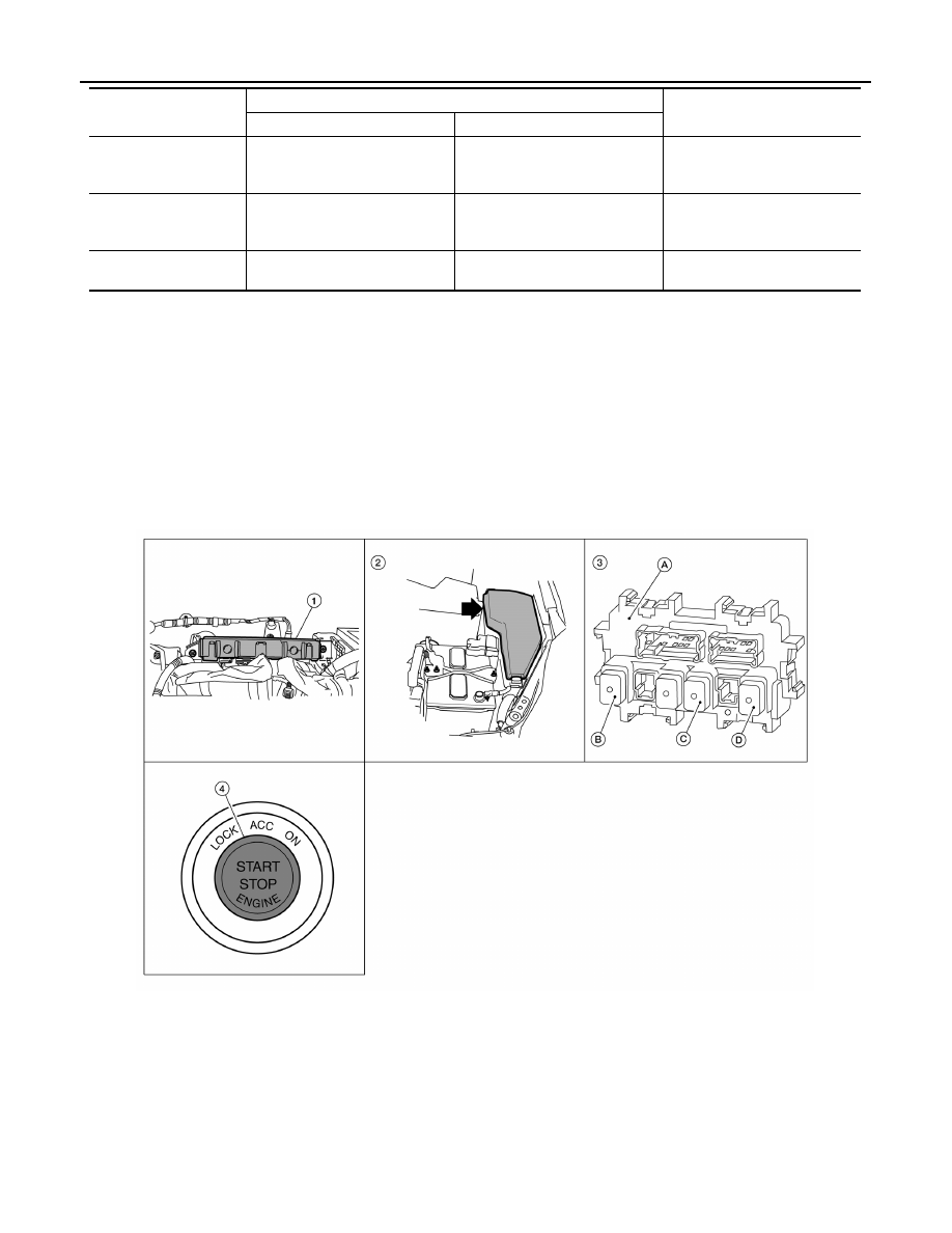
Component Parts Location

INFOID:0000000009467121

Engine is running 

→ 

OFF
(Engine stop)

Any position

1

Engine is running 

→ 

ACC
(Engine stop)

Any position other than P (*2)

1

Engine stall return oper-
ation while driving

N  position

1

Power supply position

Engine start/stop condition

Push-button ignition switch op-

eration frequency

Brake pedal

CVT selector lever position

AWMIA1192ZZ

1.

BCM M16, M17, M18, M19, M21 (view 
with instrument panel removed)

2.

IPDM E/R E16, E17, E18 (contains 
IGN relay-1)

3.

A. Fuse block (J/B) M3, M4, M5, E6
B. IGN relay-2
C. ACC relay-1
D. Front blower motor relay

4.

Push-button ignition switch M38

PCS

POWER DISTRIBUTION SYSTEM

PCS-41

< SYSTEM DESCRIPTION >

[POWER DISTRIBUTION SYSTEM]

C

D

E

F

G

H

I

J

K

L

B

A

O

P

N

Component Description

INFOID:0000000009467122

BCM

Reference

IPDM E/R

PCS-4, "System Diagram"

Ignition relay-1 (Built-in IPDM E/R)

PCS-59, "Description"

Ignition relay-2 (Built-in fuse block (J/B))

PCS-56, "Description"

Accessory relay-1

PCS-50, "Description"

Front blower motor relay

PCS-53, "Description"

Stop lamp

SEC-43, "Description"

Transmission range switch

SEC-59, "Description"

Push-button ignition switch

SEC-46, "Description"

PCS-42

< SYSTEM DESCRIPTION >

[POWER DISTRIBUTION SYSTEM]

DIAGNOSIS SYSTEM (BCM)

DIAGNOSIS SYSTEM (BCM)

COMMON ITEM
COMMON ITEM : CONSULT Function (BCM - COMMON ITEM)

INFOID:0000000010049504

APPLICATION ITEM

CONSULT performs the following functions via CAN communication with BCM.

SYSTEM APPLICATION

BCM can perform the following functions.

BCM

Direct Diagnostic Mode

Description

Ecu Identification

The BCM part number is displayed.

Self Diagnostic Result

Displays the diagnosis results judged by BCM.

Data Monitor

The BCM input/output signals are displayed.

Active Test

The signals used to activate each device are forcibly supplied from BCM.

Work support

Changes the setting for each system function.

Configuration

• Enables to read and save the vehicle specification.
• Enables to write the vehicle specification when replacing BCM.

CAN Diag Support Mntr

Monitors the reception status of CAN communication viewed from BCM.

System

Sub System

Direct Diagnostic Mode

E

cu

 Id

en

tifi

ca

tio

n

Se

lf Di

ag

no

st

ic Re

su

lt

Da

ta

 Mo

ni

tor

A

cti

ve

 T

est

W

o

rk support

Co

nf

igu

rat

ion

CA

N Diag

 Su

pp

ort Mn

tr

Door lock

DOOR LOCK

×

×

×

×

Rear window defogger

REAR DEFOGGER

×

×

Warning chime

BUZZER

×

×

Interior room lamp timer

INT LAMP

×

×

×

Exterior lamp

HEADLAMP

×

×

×

Wiper and washer

WIPER

×

×

×

Turn signal and hazard warning lamps FLASHER

×

×

×

Intelligent Key system

INTELLIGENT KEY

×

×

×

Combination switch

COMB SW

×

BCM

BCM

×

×

×

×

×

Immobilizer

IMMU

×

×

×

Interior room lamp battery saver

BATTERY SAVER

×

×

×

Trunk open

TRUNK

×

×

Vehicle security system

THEFT ALM

×

×

×

RAP system

RETAINED PWR

×

Signal buffer system

SIGNAL BUFFER

×

×

TPMS

AIR PRESSURE MONITOR

×

×

×

×

PCS

DIAGNOSIS SYSTEM (BCM)

PCS-43

< SYSTEM DESCRIPTION >

[POWER DISTRIBUTION SYSTEM]

C

D

E

F

G

H

I

J

K

L

B

A

O

P

N

BCM : CONSULT Function (BCM - BCM)

INFOID:0000000010049505

ECU IDENTIFICATION

The BCM part number is displayed.

SELF DIAGNOSTIC RESULT

Refer to 

BCS-64, "DTC Index"

.

WORK SUPPORT

CONFIGURATION

Refer to 

BCS-6, "CONFIGURATION (BCM) : Description"

.

CAN DIAG SUPPORT MNTR

Refer to 

LAN-12, "CAN Diagnostic Support Monitor"

.

Support Item

Setting

Description

RESET SETTING VALUE

Reset

Returns BCM to initial value in factory shipment.

Cancel

Cancels the reset function.


Content   ..  888  889  890  891   ..