Nissan Maxima. Manual - part 889
PCS-36
< BASIC INSPECTION >
[POWER DISTRIBUTION SYSTEM]
DIAGNOSIS AND REPAIR WORKFLOW
BASIC INSPECTION
DIAGNOSIS AND REPAIR WORKFLOW
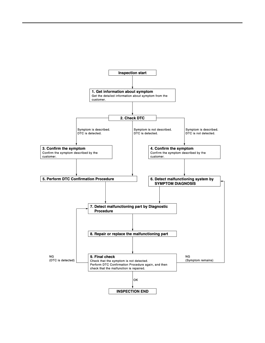
Work Flow
INFOID:0000000010049497
OVERALL SEQUENCE
DETAILED FLOW
JMKIA3449GB
|
|
|
PCS-36 < BASIC INSPECTION > [POWER DISTRIBUTION SYSTEM] DIAGNOSIS AND REPAIR WORKFLOW BASIC INSPECTION DIAGNOSIS AND REPAIR WORKFLOW Work Flow INFOID:0000000010049497 OVERALL SEQUENCE DETAILED FLOW JMKIA3449GB |