Nissan Maxima. Manual - part 877


  Index      Nissan     Nissan Maxima (2009-2014 year) - Service and Repair Manual


Search            


Content   ..  875  876  877  878   ..


Nissan Maxima. Manual - part 877


MWI

METER CONTROL SWITCH

MWI-123

< REMOVAL AND INSTALLATION >

C

D

E

F

G

H

I

J

K

L

M

B

A

O

P

METER CONTROL SWITCH

Removal and Installation

INFOID:0000000009465122

REMOVAL

1. Disconnect the negative battery terminal. Refer to 

PG-67, "Removal and Installation (Battery)"

.

2. Remove the cluster lid A. Refer to 

IP-16, "Removal and Installation"

.

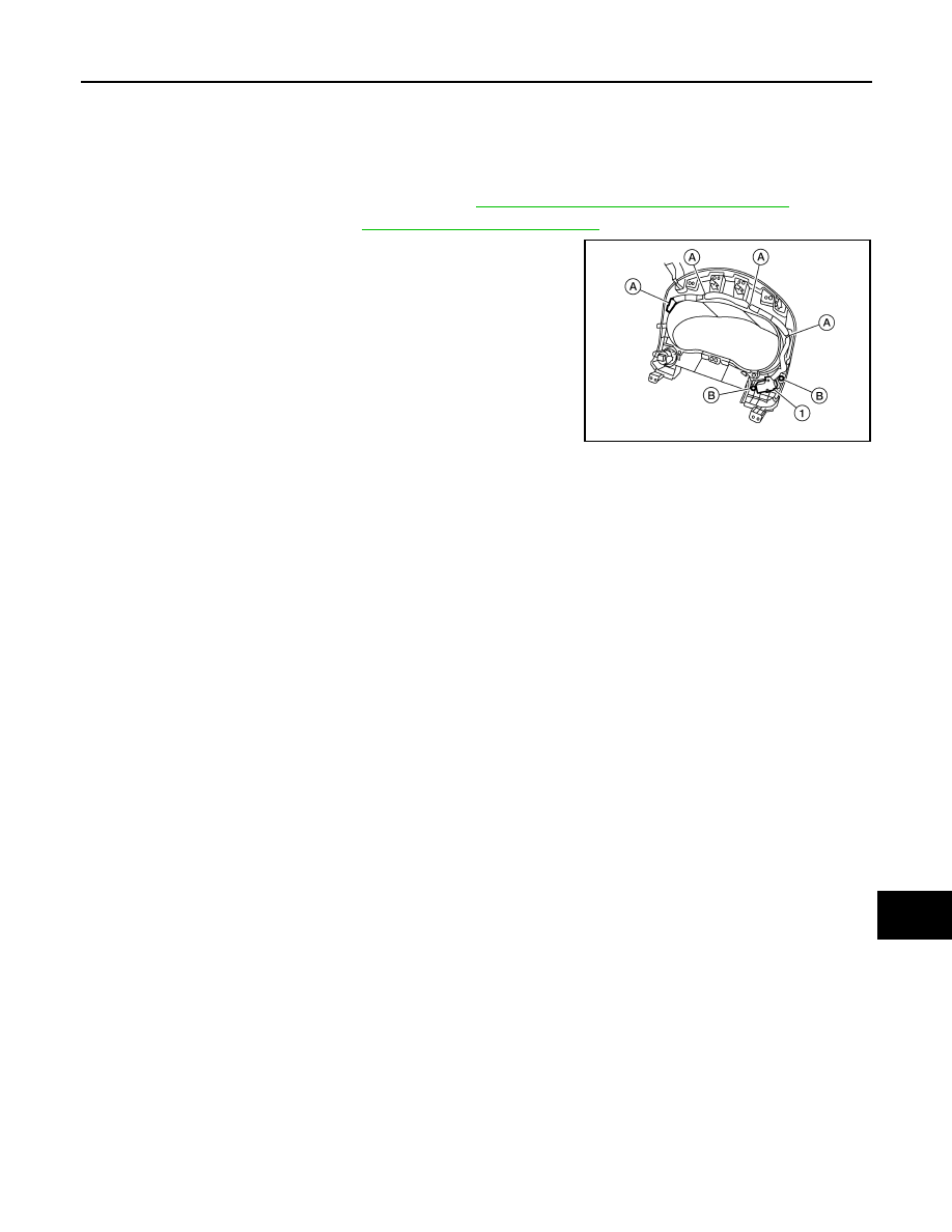
3. Detach the combination meter control switch harness clips (A).
4. Remove the combination meter control switch screws (B) and

remove the combination meter control switch (1).

INSTALLATION

Installation is in the reverse order of removal.

ALNIA1138ZZ

MWI-124

< UNIT DISASSEMBLY AND ASSEMBLY >

COMBINATION METER

UNIT DISASSEMBLY AND ASSEMBLY

COMBINATION METER

Disassembly and Assembly

INFOID:0000000009465123

DISASSEMBLY

1. Remove the combination meter. Refer to 

MWI-122, "Removal and Installation"

.

2. Remove the combination meter lens (1) from the combination

meter (2).

ASSEMBLY

Assembly is in the reverse order of disassembly.

ALLIA0007ZZ

PB-1

BRAKES

C

D

E

G

H

I

J

K

L

M

SECTION 

PB

A

B

PB

N

O

P

CONTENTS

PARKING BRAKE SYSTEM

PRECAUTION ...............................................

2

PRECAUTIONS ...................................................

2

Precaution for Supplemental Restraint System 
(SRS) "AIR BAG" and "SEAT BELT PRE-TEN-
SIONER" .................................................................
..

2

PREPARATION ............................................

3

PREPARATION ...................................................

3

Commercial Service Tool  ..........................................

3

PERIODIC MAINTENANCE ..........................

4

PARKING BRAKE SYSTEM ...............................

4

On-Vehicle Service  ...................................................

4

REMOVAL AND INSTALLATION ................

6

PARKING BRAKE CONTROL ...........................

6

Exploded View ..........................................................

6

Removal and Installation  ..........................................

6

PARKING BRAKE SHOE  ..................................

8

Exploded View ..........................................................

8

Removal and Installation  ..........................................

8

SERVICE DATA AND SPECIFICATIONS 
(SDS) ............................................................

11

SERVICE DATA AND SPECIFICATIONS 
(SDS) .................................................................

11

Parking Brake Control  .............................................

11

Parking Drum Brake  ................................................

11

PB-2

< PRECAUTION >

PRECAUTIONS

PRECAUTION

PRECAUTIONS

Precaution for Supplemental Restraint System (SRS) "AIR BAG" and "SEAT BELT 
PRE-TENSIONER"

INFOID:0000000009466619

The Supplemental Restraint System such as “AIR BAG” and “SEAT BELT PRE-TENSIONER”, used along

with a front seat belt, helps to reduce the risk or severity of injury to the driver and front passenger for certain

types of collision. This system includes seat belt switch inputs and dual stage front air bag modules. The SRS

system uses the seat belt switches to determine the front air bag deployment, and may only deploy one front

air bag, depending on the severity of a collision and whether the front occupants are belted or unbelted.

Information necessary to service the system safely is included in the SR and SB section of this Service Man-

ual.

WARNING:

• To avoid rendering the SRS inoperative, which could increase the risk of personal injury or death in

the event of a collision which would result in air bag inflation, all maintenance must be performed by

an authorized NISSAN/INFINITI dealer.

• Improper maintenance, including incorrect removal and installation of the SRS, can lead to personal

injury caused by unintentional activation of the system. For removal of Spiral Cable and Air Bag

Module, see the SR section.

• Do not use electrical test equipment on any circuit related to the SRS unless instructed to in this

Service Manual. SRS wiring harnesses can be identified by yellow and/or orange harnesses or har-

ness connectors.

PRECAUTIONS WHEN USING POWER TOOLS (AIR OR ELECTRIC) AND HAMMERS

WARNING:

• When working near the Airbag Diagnosis Sensor Unit or other Airbag System sensors with the Igni-

tion ON or engine running, DO NOT use air or electric power tools or strike near the sensor(s) with a

hammer. Heavy vibration could activate the sensor(s) and deploy the air bag(s), possibly causing

serious injury.

• When using air or electric power tools or hammers, always switch the Ignition OFF, disconnect the

battery and wait at least 3 minutes before performing any service.


Content   ..  875  876  877  878   ..