Nissan Maxima. Manual - part 820


  Index      Nissan     Nissan Maxima (2009-2014 year) - Service and Repair Manual


Search            


Content   ..  818  819  820  821   ..


Nissan Maxima. Manual - part 820


LAN-92

< DTC/CIRCUIT DIAGNOSIS >

[CAN SYSTEM (TYPE 3)]

ECM BRANCH LINE CIRCUIT

ECM BRANCH LINE CIRCUIT

Diagnosis Procedure

INFOID:0000000009990325

1.

CHECK CONNECTOR

1. Turn the ignition switch OFF.

2. Disconnect the battery cable from the negative terminal.

3. Check the following terminals and connectors for damage, bend and loose connection (unit side and con-

nector side).

-

Models without automatic drive positioner

ECM

Harness connector E30

Harness connector M1

-

Models with automatic drive positioner

ECM

Harness connector E29

Harness connector B10

Is the inspection result normal?

YES

>> GO TO 2.

NO

>> Repair the terminal and connector.

2.

CHECK HARNESS FOR OPEN CIRCUIT

1. Disconnect the connector of ECM.

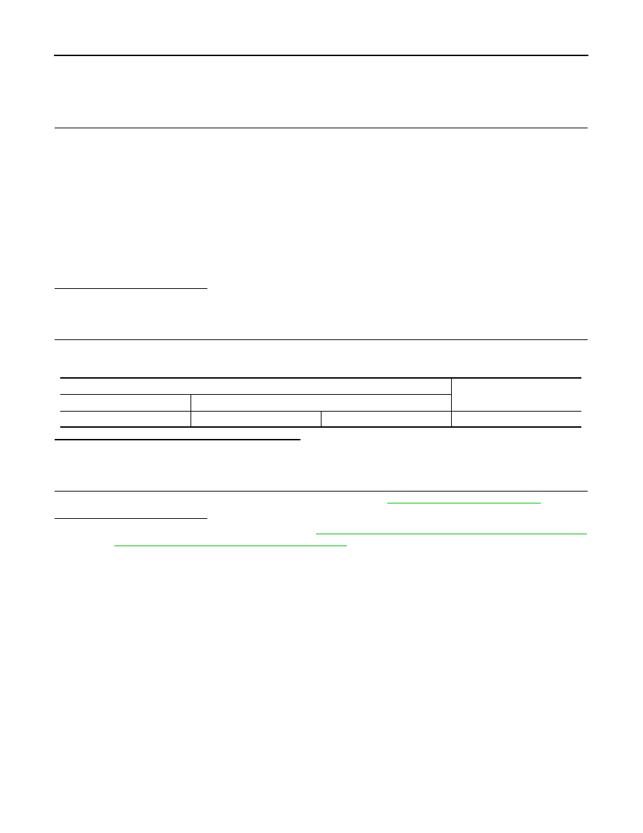
2. Check the resistance between the ECM harness connector terminals.

Is the measurement value within the specification?

YES

>> GO TO 3.

NO

>> Repair the ECM branch line.

3.

CHECK POWER SUPPLY AND GROUND CIRCUIT

Check the power supply and the ground circuit of the ECM. Refer to 

EC-157, "Diagnosis Procedure"

.

Is the inspection result normal?

YES (Present error)>>Replace the ECM. Refer to 

EC-17, "ADDITIONAL SERVICE WHEN REPLACING

CONTROL UNIT : Special Repair Requirement"

.

YES (Past error)>>Error was detected in the ECM branch line.

NO

>> Repair the power supply and the ground circuit.

ECM harness connector

Resistance (

Ω)

Connector No.

Terminal No.

E10

98

97

Approx. 108 – 132

LAN

ADP BRANCH LINE CIRCUIT

LAN-93

< DTC/CIRCUIT DIAGNOSIS >

[CAN SYSTEM (TYPE 3)]

C

D

E

F

G

H

I

J

K

L

B

A

O

P

N

ADP BRANCH LINE CIRCUIT

Diagnosis Procedure

INFOID:0000000009990326

1.

CHECK CONNECTOR

1. Turn the ignition switch OFF.

2. Disconnect the battery cable from the negative terminal.

3. Check the following terminals and connectors for damage, bend and loose connection (unit side and con-

nector side).

-

Driver seat control unit

-

Harness connector B208

-

Harness connector B32

Is the inspection result normal?

YES

>> GO TO 2.

NO

>> Repair the terminal and connector.

2.

CHECK HARNESS FOR OPEN CIRCUIT

1. Disconnect the connector of driver seat control unit.

2. Check the resistance between the driver seat control unit harness connector terminals.

Is the measurement value within the specification?

YES

>> GO TO 3.

NO

>> Repair the driver seat control unit branch line.

3.

CHECK POWER SUPPLY AND GROUND CIRCUIT

Check the power supply and the ground circuit of the driver seat control unit. Refer to 

ADP-47, "DRIVER SEAT

CONTROL UNIT : Diagnosis Procedure"

.

Is the inspection result normal?

YES (Present error)>>Replace the driver seat control unit. Refer to 

ADP-169, "Removal and Installation"

.

YES (Past error)>>Error was detected in the driver seat control unit branch line.

NO

>> Repair the power supply and the ground circuit.

Driver seat control unit harness connector

Resistance (

Ω)

Connector No.

Terminal No.

B203

16

32

Approx. 54 – 66

LAN-94

< DTC/CIRCUIT DIAGNOSIS >

[CAN SYSTEM (TYPE 3)]

BCM BRANCH LINE CIRCUIT

BCM BRANCH LINE CIRCUIT

Diagnosis Procedure

INFOID:0000000009990327

1.

CHECK CONNECTOR

1. Turn the ignition switch OFF.

2. Disconnect the battery cable from the negative terminal.

3. Check the terminals and connectors of the BCM for damage, bend and loose connection (unit side and

connector side).

Is the inspection result normal?

YES

>> GO TO 2.

NO

>> Repair the terminal and connector.

2.

CHECK HARNESS FOR OPEN CIRCUIT

1. Disconnect the connector of BCM.

2. Check the resistance between the BCM harness connector terminals.

Is the measurement value within the specification?

YES

>> GO TO 3.

NO

>> Repair the BCM branch line.

3.

CHECK POWER SUPPLY AND GROUND CIRCUIT

Check the power supply and the ground circuit of the BCM. Refer to 

BCS-36, "Diagnosis Procedure"

.

Is the inspection result normal?

YES (Present error)>>Replace the BCM. Refer to 

BCS-79, "Removal and Installation"

.

YES (Past error)>>Error was detected in the BCM branch line.

NO

>> Repair the power supply and the ground circuit.

BCM harness connector

Resistance (

Ω)

Connector No.

Terminal No.

M19

79

78

Approx. 54 – 66

LAN

DLC BRANCH LINE CIRCUIT

LAN-95

< DTC/CIRCUIT DIAGNOSIS >

[CAN SYSTEM (TYPE 3)]

C

D

E

F

G

H

I

J

K

L

B

A

O

P

N

DLC BRANCH LINE CIRCUIT

Diagnosis Procedure

INFOID:0000000009990328

1.

CHECK CONNECTOR

1. Turn the ignition switch OFF.

2. Disconnect the battery cable from the negative terminal.

3. Check the terminals and connectors of the data link connector for damage, bend and loose connection

(connector side and harness side).

Is the inspection result normal?

YES

>> GO TO 2.

NO

>> Repair the terminal and connector.

2.

CHECK HARNESS FOR OPEN CIRCUIT

Check the resistance between the data link connector terminals.

Is the measurement value within the specification?

YES (Present error)>>Check CAN system type decision again.

YES (Past error)>>Error was detected in the data link connector branch line circuit.

NO

>> Repair the data link connector branch line.

Data link connector

Resistance (

Ω)

Connector No.

Terminal No.

M22

6

14

Approx. 54 – 66


Content   ..  818  819  820  821   ..