Nissan Maxima. Manual - part 714


  Index      Nissan     Nissan Maxima (2009-2014 year) - Service and Repair Manual


Search            


Content   ..  712  713  714  715   ..


Nissan Maxima. Manual - part 714


HAC-32

< DTC/CIRCUIT DIAGNOSIS >

[WITH COLOR DISPLAY]

B257B, B257C AMBIENT SENSOR

B257B, B257C AMBIENT SENSOR

Description

INFOID:0000000010050970

COMPONENT DESCRIPTION
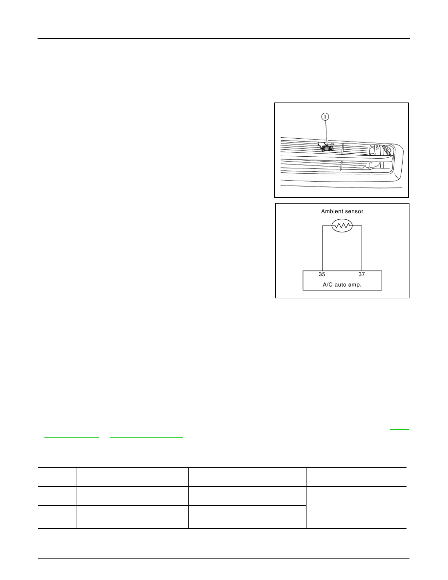
Ambient Sensor

• The ambient sensor (1) is installed to the front bumper reinforce-

ment. 

• It detects ambient temperature and converts it into a resistance

value which is then input into the A/C auto amp.

Ambient Sensor Circuit

AMBIENT TEMPERATURE INPUT PROCESS

The A/C auto amp. equips a processing circuit for the ambient sensor input. However, when the temperature

detected by the ambient sensor increases quickly, the processing circuit retards the A/C auto amp. function. It

only allows the A/C auto amp. to recognize an ambient temperature increase of 0.33

°C (0.6°F) per 100 sec-

onds.

As an example, consider stopping for a few minutes after high-speed driving. Although the actual ambient

temperature has not changed, the temperature detected by the ambient sensor increases. This is because the

heat from the engine compartment can radiate to the front bumper area, the location of the ambient sensor.

DTC Logic

INFOID:0000000010050971

DTC DETECTION LOGIC

NOTE:

• If DTC is displayed along with DTC U1000 or U1010, first diagnose the DTC U1000 or U1010. Refer to 

HAC-

30, "DTC Logic"

 or 

HAC-31, "DTC Logic"

• If there is an open circuit in the ambient sensor, A/C auto amp. registers extreme cold [-30

°C (-22°F)] and

adjusts the temperature control warmer. 

DTC CONFIRMATION PROCEDURE

1.

CHECK WITH SELF-DIAGNOSIS FUNCTION OF CONSULT

ALIIA0314ZZ

JPIIA0612GB

DTC

Items

 (CONSULT screen terms)

Diagnostic item is detected when...

Possible cause

B257B

AMB TEMP SEN (SHORT)

Detected temperature at ambient sensor 
55

°C (131°F) or more

• Ambient sensor
• A/C auto amp.
• Harness and connector

(Ambient sensor circuit is open, 
or there is a short in the circuit)

B257C

AMB TEMP SEN (OPEN)

Detected temperature at ambient sensor 
-30

°C (-22°F) or less

B257B, B257C AMBIENT SENSOR

HAC-33

< DTC/CIRCUIT DIAGNOSIS >

[WITH COLOR DISPLAY]

C

D

E

F

G

H

J

K

L

M

A

B

HAC

N

O

P

1. Using CONSULT, perform “SELF-DIAGNOSIS RESULTS” of HVAC. 

2. Check if any DTC No. is displayed in the self-diagnosis results. 

NOTE:

• If DTC is displayed along with DTC U1000 or U1010, first diagnose the DTC U1000 or U1010. Refer to 

HAC-

30, "DTC Logic"

 or 

HAC-31, "DTC Logic"

• If there is an open circuit in the ambient sensor, A/C auto amp. registers extreme cold [-30

°C (-22°F)] and

adjusts the temperature control warmer. 

Is DTC No.“B257B” or “B257C” displayed?

YES

>> Perform trouble diagnosis for the ambient sensor. Refer to 

HAC-33, "Diagnosis Procedure"

NO

>> Inspection End.

Diagnosis Procedure

INFOID:0000000010050972

Regarding Wiring Diagram information, refer to 

HAC-67, "Wiring Diagram - With Color Display"

.

1.

CHECK VOLTAGE BETWEEN AMBIENT SENSOR AND GROUND

1. Disconnect ambient sensor connector.

2. Turn ignition switch ON.

3. Check voltage between ambient sensor harness connector

E211 terminal 1 and ground.

Is the inspection result normal?

YES

>> GO TO 2.

NO

>> GO TO 4.

2.

CHECK CONTINUITY BETWEEN AMBIENT SENSOR AND A/C AUTO AMP. 

1. Turn ignition switch OFF.

2. Disconnect A/C auto amp. connector.

3. Check continuity between ambient sensor harness connector

E211 (A) terminal 2 and A/C auto amp. harness connector

M37(B) terminal 37.

Is the inspection result normal?

YES

>> GO TO 3.

NO

>> Repair harness or connector.

3.

CHECK AMBIENT SENSOR

Check ambient sensor. Refer to 

HAC-34, "Component Inspection"

.

Is the inspection result normal?

YES

>> Replace A/C auto amp. Refer to 

HAC-100, "Removal and Installation"

.

NO

>> Replace ambient sensor. Refer to 

HAC-101, "Removal and Installation"

.

4.

CHECK CONTINUITY BETWEEN AMBIENT SENSOR AND A/C AUTO AMP.

1 - Ground

: Approx. 5V

AWIIA1133ZZ

2 - 37

: Continuity should exist.

AWIIA1134ZZ

HAC-34

< DTC/CIRCUIT DIAGNOSIS >

[WITH COLOR DISPLAY]

B257B, B257C AMBIENT SENSOR

1. Turn ignition switch OFF.

2. Disconnect A/C auto amp. connector.

3. Check continuity between ambient sensor harness connector

E211 (A) terminal 1 and A/C auto amp. harness connector M37

(B) terminal 35.

4. Check continuity between ambient sensor harness connector

E211 (A) terminal 1 and ground.

Is the inspection result normal?

YES

>> Replace A/C auto amp. Refer to 

HAC-100, "Removal and Installation"

.

NO

>> Repair harness or connector.

Component Inspection

INFOID:0000000010050973

1.

CHECK AMBIENT SENSOR

1. Turn ignition switch OFF.

2. Disconnect ambient sensor connector. 

3. Check resistance between ambient sensor terminals.

Is the inspection result normal?

YES

>> Inspection End.

NO

>> Replace ambient sensor. Refer to 

HAC-101, "Removal and Installation"

.

1 - 35

: Continuity should exist.

1 - Ground

: Continuity should not exist.

AWIIA1135ZZ

Terminal

Condition

Resistance k

Temperature 

°C (°F)

1

2

−15 (5)

12.73

−10 (14)

9.92

−5 (23)

7.80

0 (32)

6.19

5 (41)

4.95

10 (50)

3.99

15 (59)

3.24

20 (68)

2.65

25 (77)

2.19

30 (86)

1.81

35 (95)

1.51

40 (104)

1.27

45 (113)

1.07

B2578, B2579 IN-VEHICLE SENSOR

HAC-35

< DTC/CIRCUIT DIAGNOSIS >

[WITH COLOR DISPLAY]

C

D

E

F

G

H

J

K

L

M

A

B

HAC

N

O

P

B2578, B2579 IN-VEHICLE SENSOR

Description

INFOID:0000000010050974

In-vehicle Sensor

• The in-vehicle sensor (1) is located on instrument lower cover

(LH). 

• It converts variations in compartment air temperature drawn from

the aspirator into a resistance value. It is then input into the A/C

auto amp.

In-vehicle Sensor Circuit

Aspirator

The aspirator (1) is located on driver side of heater & cooling unit

assembly. It produces vacuum pressure due to air discharged from

the heater & cooling unit assembly, continuously taking compartment

air in the aspirator.

DTC Logic

INFOID:0000000010050975

DTC DETECTION LOGIC

AWIIA1055ZZ

JPIIA0613GB

AWIIA0049ZZ

RJIA1804E


Content   ..  712  713  714  715   ..