Nissan Maxima. Manual - part 712
HAC-24
< SYSTEM DESCRIPTION >
[WITH COLOR DISPLAY]
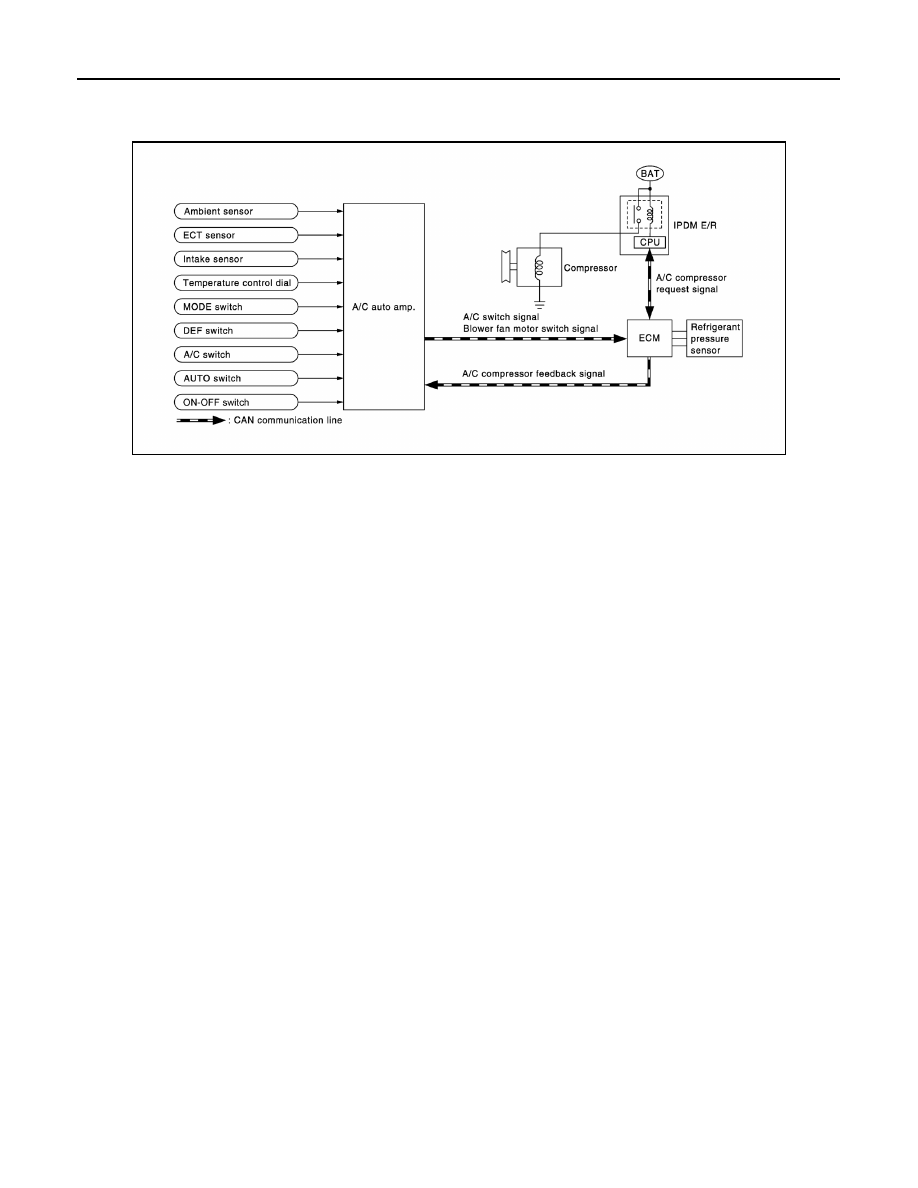
MAGNET CLUTCH CONTROL SYSTEM
MAGNET CLUTCH CONTROL SYSTEM
System Diagram
INFOID:0000000010050960
System Description
INFOID:0000000010050961
The A/C auto amp. controls compressor operation by ambient temperature, intake air temperature and signal
from ECM.
SYSTEM OPERATION
When the A/C switch, the AUTO switch, or the DEF switch is pressed, or when shifting mode position to D/F,
the A/C auto amp. transmits the A/C switch signal and blower fan motor switch signal to the ECM, via CAN
communication.
ECM judges whether compressor can be turned ON, based on each sensor status (refrigerant-pressure sen-
sor signal, throttle angle, etc.). If the ECM judges that the compressor can be turned ON, it sends A/C com-
pressor request signal to the IPDM E/R, via CAN communication.
Upon receipt of A/C compressor request signal from the ECM, the IPDM E/R turns the A/C relay ON to oper-
ate the compressor.
When sending A/C compressor request signal to the IPDM E/R via CAN communication line, the ECM simul-
taneously sends A/C compressor feedback signal to A/C auto amp. via CAN communication line.
The ECM sends A/C compressor feedback signal to A/C auto amp., then, uses input A/C compressor feed-
back signal to control air inlet.
Compressor Protection Control
The ECM makes the A/C relay turn OFF and stops the compressor when pressure on the high-pressure side,
detected by the refrigerant pressure sensor, is over approximately 3,119 kPa (31.8 kg/cm
2
, 452 psi), or below
approximately 118 kPa (1.2 kg/cm
2
, 17 psi).
Low Temperature Protection Control
Turn the A/C relay to OFF and stop the A/C compressor by the signal from the A/C auto amp., according to the
evaporator passing air temperature detected by the intake sensor and the ambient temperature detected by
the ambient sensor.
AWIIA1380GB