Nissan Maxima. Manual - part 695


  Index      Nissan     Nissan Maxima (2009-2014 year) - Service and Repair Manual


Search            


Content   ..  693  694  695  696   ..


Nissan Maxima. Manual - part 695


HA-6

< PRECAUTION >

PRECAUTIONS

• Connect the pipes at the final stage of the operation when installing an air conditioner in the vehicle.

Do not remove the seal caps of pipes and other components until just before required for connec-

tion.

• Allow components stored in cool areas to warm to working area temperature before removing seal

caps. This prevents condensation from forming inside A/C components.

• Remove moisture thoroughly from the refrigeration system before charging the refrigerant.

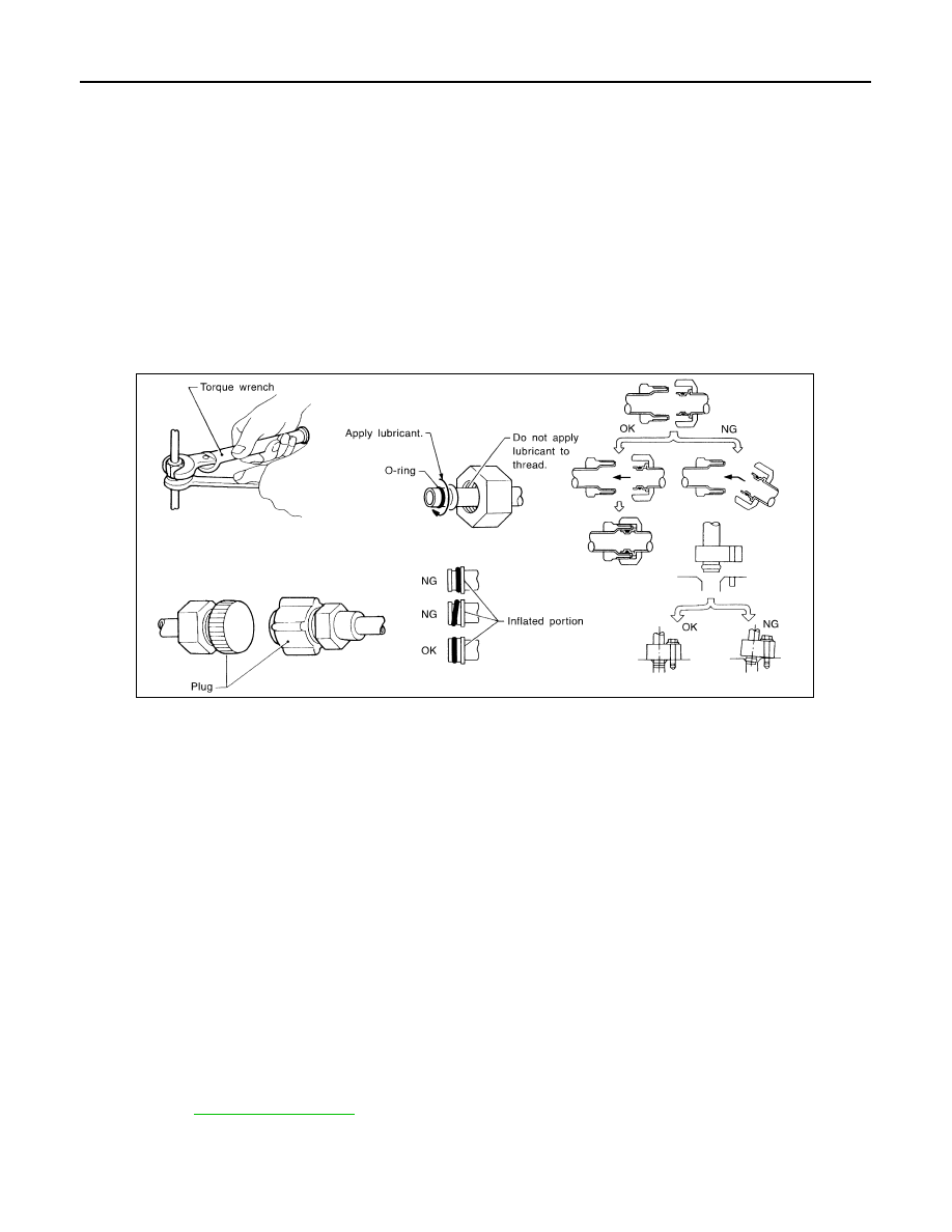
• Always replace used O-rings.

• Apply oil to circle of the O-rings shown in illustration when connecting tube. Be careful not to apply

oil to threaded portion.

• O-ring must be closely attached to the groove portion of tube.

• Be careful not to damage O-ring and tube when replacing the O-ring.

• Connect tube until a click can be heard. Then tighten the nut or bolt by hand. Check that the O-ring is

installed to tube correctly.

• Perform leakage test and make sure that there is no leakage from connections after connecting line.

Disconnect that line and replace the O-ring when the refrigerant leaking point is found. Then tighten

connections of seal seat to the specified torque.

CONTAMINATED REFRIGERANT

Take appropriate steps shown below if a refrigerant other than pure HFC-134a (R-134a) is identified in

a vehicle:

• Explain to the customer that environmental regulations prohibit the release of contaminated refrigerant into

the atmosphere.

• Explain that recovery of the contaminated refrigerant could damage service equipment and refrigerant sup-

ply.

• Suggest the customer return the vehicle to the location of previous service where the contamination may

have occurred.

• In case of repairing, recover the refrigerant using only dedicated equipment and containers. Do not

recover contaminated refrigerant into the existing service equipment. Contact a local refrigerant prod-

uct retailer for available service if the facility does not have dedicated recovery equipment. This refrigerant

must be disposed of in accordance with all federal and local regulations. In addition, replacement of all

refrigerant system components on the vehicle is recommended.

• The air conditioner warranty is void if the vehicle is within the warranty period. Please contact Nissan Cus-

tomer Affairs for further assistance.

COMPRESSOR

CAUTION:

• Plug all openings to prevent moisture and foreign matter from entering.

• Store it in the same way as it is when mounted on the car when the compressor is removed.

• Follow “Maintenance of Oil Quantity in Compressor” exactly when replacing or repairing compres-

sor. Refer to 

HA-30, "Description"

.

• Keep friction surfaces between clutch and pulley clean. Wipe it off by using a clean waste cloth

moistened with thinner if the surface is contaminated with oil.

RHA861F

PRECAUTIONS

HA-7

< PRECAUTION >

C

D

E

F

G

H

J

K

L

M

A

B

HA

N

O

P

• Turn the compressor shaft by hand more than five turns in both directions after compressor service

operation. This distributes oil equally inside the compressor. Let the engine idle and operate the

compressor for one hour after the compressor is installed.

• Apply voltage to the new one and check for normal operation after replacing the compressor magnet

clutch.

LEAK DETECTION DYE

CAUTION:

• The A/C system contains a fluorescent leak detection dye used for locating refrigerant leakages. An

ultraviolet (UV) lamp is required to illuminate the dye when inspecting for leakages.

• Always wear fluorescence enhancing UV safety goggles to protect eyes and enhance the visibility of

the fluorescent dye.

• The fluorescent dye leak detector is not a replacement for an electrical leak detector (SST: J-41995).

The fluorescent dye leak detector should be used in conjunction with an electrical leak detector

(SST: J-41995) to pin-point refrigerant leakages.

• Read and follow all manufacture’s operating instructions and precautions prior to performing the

work for the purpose of safety and customer’s satisfaction.

• A compressor shaft seal should not necessarily be repaired because of dye seepage. The compres-

sor shaft seal should only be repaired after confirming the leakage with an electrical leak detector

(SST: J-41995).

• Always remove any remaining dye from the leakage area after repairs are completed to avoid a mis-

diagnosis during a future service.

• Do not allow dye to come into contact with painted body panels or interior components. Clean imme-

diately with the approved dye cleaner if dye is spilled. Fluorescent dye left on a surface for an

extended period of time cannot be removed.

• Do not spray the fluorescent dye cleaning agent on hot surfaces (engine exhaust manifold, etc.).

• Do not use more than one refrigerant dye bottle [1/4 ounce (7.4 cc)] per A/C system.

• Leak detection dyes for HFC-134a (R-134a) and CFC-12 (R-12) A/C systems are different. Do not use

HFC-134a (R-134a) leak detection dye in CFC-12 (R-12) A/C system or CFC-12 (R-12) leak detection

dye in HFC-134a (R-134a) A/C system or A/C system damage may result.

• The fluorescent properties of the dye remains for three or more years unless a compressor malfunc-

tion occurs.

NOTE:

Identification

• Vehicles with factory installed fluorescent dye have a green label.

• Vehicles without factory installed fluorescent dye have a blue label.

Service Equipment

INFOID:0000000009465919

RECOVERY/RECYCLING RECHARGING EQUIPMENT

Be certain to follow the manufacturer’s instructions for machine operation and machine maintenance. Do not

introduce any refrigerant other than that specified into the machine.

ELECTRICAL LEAK DETECTOR

Be certain to follow the manufacturer’s instructions for tester operation and tester maintenance.

VACUUM PUMP

HA-8

< PRECAUTION >

PRECAUTIONS

The oil contained inside the vacuum pump is not compatible with the

specified oil for HFC-134a (R-134a) A/C systems. The vent side of

the vacuum pump is exposed to atmospheric pressure, so the vac-

uum pump oil may migrate out of the pump into the service hose.

This is possible when the pump is switched OFF after evacuation

(vacuuming) and hose is connected to it.

To prevent this migration, use a manual valve placed near the hose-

to-pump connection, as per the following.

• Vacuum pumps usually have a manual isolator valve as part of the

pump. Close this valve to isolate the service hose from the pump.

• Use a hose equipped with a manual shut-off valve near the pump

end for pumps without an isolator. Close the valve to isolate the

hose from the pump.

• Disconnect the hose from the pump if the hose has an automatic

shut-off valve. As long as the hose is connected, the valve is open

and lubricating oil may migrate.

Some one-way valves open when vacuum is applied and close

under no vacuum condition. Such valves may restrict the pump’s

ability to pull a deep vacuum and are not recommended.

MANIFOLD GAUGE SET

Be certain that the gauge face indicates HFC-134a or R-134a. Be

sure the gauge set has 1/2

″-16 ACME threaded connections for ser-

vice hoses. Confirm the set has been used only with refrigerant

HFC-134a (R-134a) and specified oils.

SERVICE HOSES

Be certain that the service hoses display the markings described

(colored hose with black stripe). All hoses must equip positive shut-

off devices (either manual or automatic) near the end of the hoses

opposite to the manifold gauge.

SERVICE COUPLERS

RHA270DA

SHA533D

RHA272D

PRECAUTIONS

HA-9

< PRECAUTION >

C

D

E

F

G

H

J

K

L

M

A

B

HA

N

O

P

Do not attempt to connect HFC-134a (R-134a) service couplers to

the CFC-12 (R-12) A/C system. The HFC-134a (R-134a) couplers

do not properly connect to the CFC-12 (R-12) system. However, if an

improper connection is attempted, discharging and contamination

may occur.

REFRIGERANT WEIGHT SCALE

Verify that no refrigerant other than HFC-134a (R-134a) and speci-

fied oils have been used with the scale. The hose fitting must be 1/

2

″-16 ACME if the scale controls refrigerant flow electronically.

CHARGING CYLINDER

Using a charging cylinder is not recommended. Refrigerant may be vented into air from cylinder’s top valve

when filling the cylinder with refrigerant. Also, the accuracy of the cylinder is generally less than that of an

electronic scale or of quality recycle/recharge equipment.

Shut-off valve rotation

A/C service valve

Clockwise

Open

Counterclockwise

Close

RHA273D

RHA274D


Content   ..  693  694  695  696   ..