Nissan Maxima. Manual - part 542
EM-56
< REMOVAL AND INSTALLATION >
FRONT TIMING CHAIN CASE
b. Position a pulley puller at recess hole of crankshaft pulley to
remove crankshaft pulley.
CAUTION:
Do not use a puller claw on the outer diameter of the crank-
shaft pulley.
23. Remove the power steering pump. Refer to
ST-28, "Removal and Installation"
.
24. Remove the generator. Refer to
CHG-28, "Removal and Installation"
.
25. Remove the A/C compressor bolts, remove the A/C compressor and position aside. Refer to
"Removal and Installation for Compressor"
.
26. Remove the generator bracket. Refer to
.
27. Support the engine (1) and transaxle (2) using a suitable jack (A)
as shown.
CAUTION:
• Position a suitable jack under the engine and transaxle
assembly as shown.
• Do not damage the front exhaust tube or transaxle oil pan
with the jack.
28. Remove engine oil cooler tube bolts and bracket.
29. Disconnect the oil pressure switch harness connector.
30. Disconnect intake valve timing control solenoid valve harness connector.
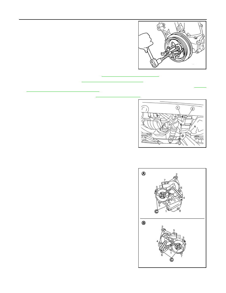
31. Remove the intake valve timing control solenoid valve cover
(RH) (bank 1) and intake valve timing control solenoid valve
cover (LH) (bank 2).
a. Loosen intake valve timing control solenoid valve cover bolts in
the reverse order as shown.
CAUTION:
The shaft in the intake valve timing control solenoid valve
cover is inserted into the center hole of the intake camshaft
sprocket. Remove the intake valve timing control solenoid
valve cover by pulling straight out until the intake valve tim-
ing control solenoid valve cover disengages from the cam-
shaft sprocket.
b. Shaft is engaged in intake camshaft sprocket center hole on inside. Pull straight out so as not to tilt until
the shaft is disengaged.
EMQ0477D
ALBIA0894GB
(A) : Intake valve timing control solenoid valve cover (RH) (bank 1)
(B) : Intake valve timing control solenoid valve cover (LH) (bank 2)
(C) : Dowel pin hole
AWBIA0720ZZ